Mitsubishi Outlander XL. Manual - part 409
INSPECTION PROCEDURE 25: A/C system.
M11310100309USA0000010000
1
ZK602874
71 72 73 74 75 76 77 78 79 80 81 82
83 84 85 86 87 88 89 90 91 92 93 94
95 96 97 98 99
100 101 102 103 104
112 113 114
109
108
107
110 111
115 116
106
105
118
117
1
2
3
4
1
10 111213 14 1516 17 1819 20
2 3 4
5 6 7 8 9
WHITE
WHITE
7
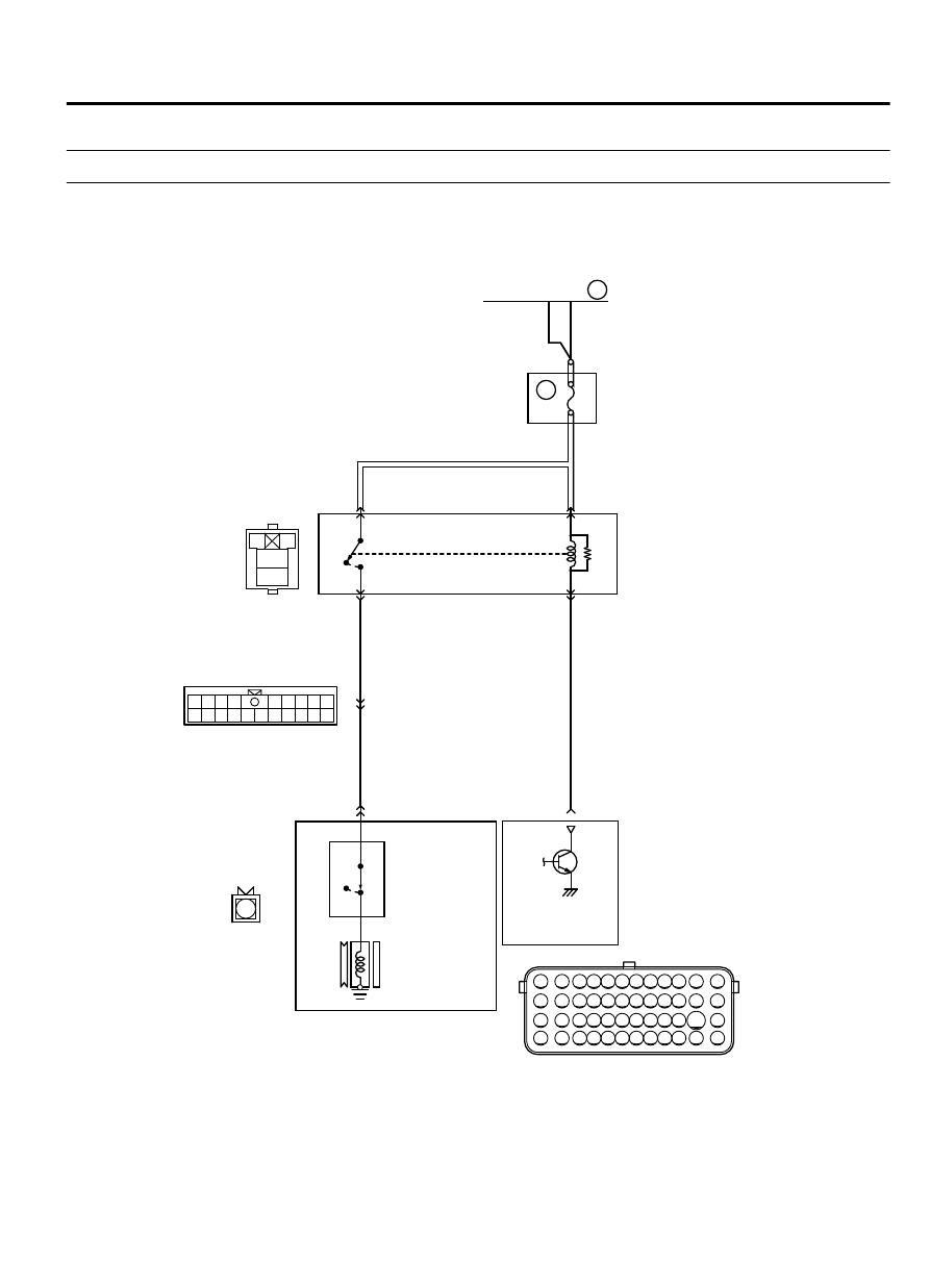
10A
ORANGE
A/C COMPRESSOR
REL AY
REL AY B OX
(ENGINE COM PARTMENT )
4
2
1
A-16X
B-17
MU802653
A-13
OFF
A/C
REFRIGERANT
TEMPER ATURE
SWITCH
A/C COMPRESSOR ASSEMB
LY
A/C
COMPRESSOR
CLUTCH
A/C COMPRESSOR RELAY CIRCUIT
102
AA00
B-11
ENGINE
CONTROL
MODULE
LIGHT GREEN
LIGHT GREEN
3
1
5
OFF
ON
ON
FUSIBLE LINK
36
MULTIPORT INJECTION SYSTEM (MFI) <DIAGNOSIS>
13Ab-831
SYMPTOM PROCEDURES