Mitsubishi Outlander XL. Manual - part 394


  Index      Mitsubishi     Mitsubishi Outlander XL - service repair manual 2007 year


Search            


Content   ..  392  393  394  395   ..


Mitsubishi Outlander XL. Manual - part 394


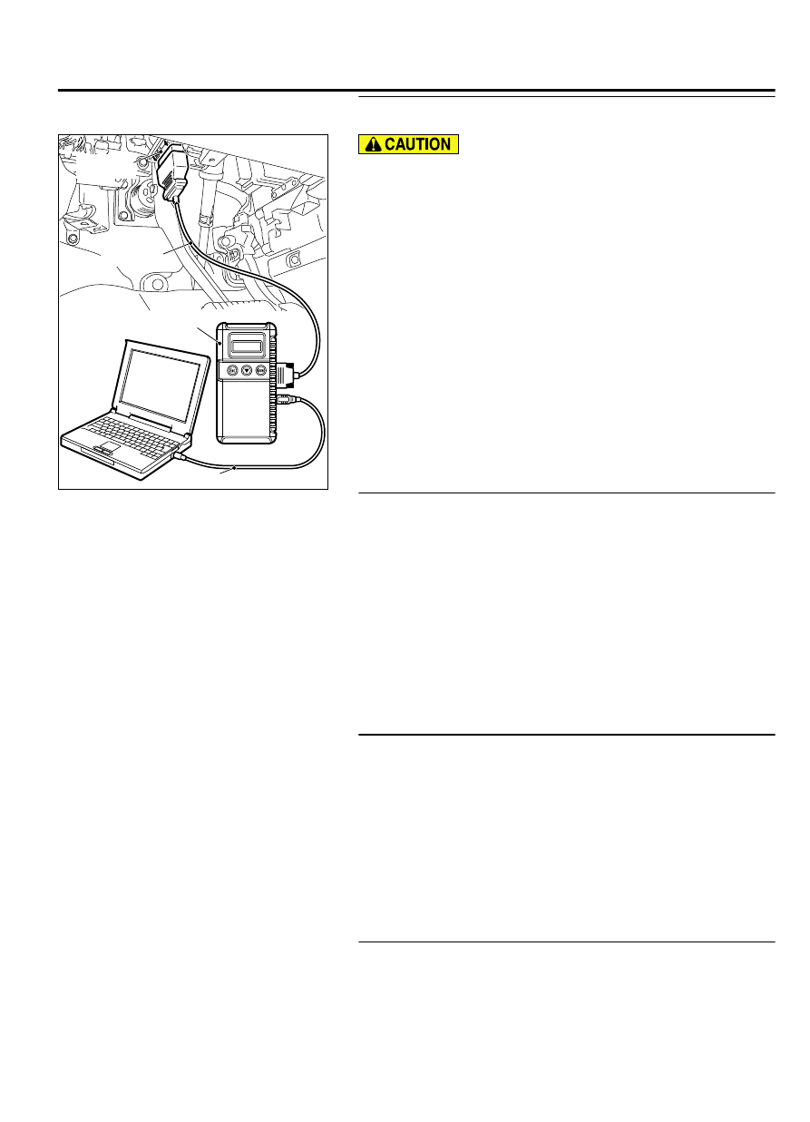
STEP 2. Using scan tool MB991958, read the diagnostic
trouble code (DTC).

ZC501967

AC404789

ZC5019680000

MB991824

MB991827

MB991910

Data link

connector

To prevent damage to scan tool MB991958, always turn the
ignition  switch  to  the  "LOCK"  (OFF)  position  before
connecting or disconnecting scan tool MB991958.

(1)

Connect scan tool MB991958 to the data link connector.

(2)

Turn the ignition switch to the "ON" position.

(3)

Read the DTC.

(4)

Turn the ignition switch the "LOCK" (OFF) position.

Q:Is any DTC set?

YES:

 Refer to Diagnostic Trouble Code Chart P.13Ab-44.

NO:

 Go to Step 3.

STEP 3. Using scan tool MB991958, check data list.

(1)

Turn the ignition switch the "ON" position.

(2)

Check the following items in the data list. Refer to Data List
Reference Table P.13Ab-837.

a
.

Item 01: Power Supply Voltage (at Cranking)

b
.

Item 06: Engine Coolant Temperature Sensor.

(3)

Turn the ignition switch the "LOCK" (OFF) position.

Q:Is the sensor operating properly?

YES:

 Go to Step 4.

NO:

 Repair or Replace. Then confirm that the malfunction

symptom is eliminated.

STEP 4. Using scan tool MB991958, check actuator test.

(1)

Turn the ignition switch to the "ON" position.

(2)

Check  the  following  items  in  the  actuator  test.  Refer  to
Actuator Test Reference Table P.13Ab-857.

a
.

Item 09: Fuel Pump.

(3)

Turn the ignition switch to the "LOCK" (OFF) position.

Q:Is the actuator operating properly?

YES:

 Go to Step 5.

NO:

 Repair or Replace. Then confirm that the malfunction

symptom is eliminated.

STEP 5. Check the ignition timing.

(1)

Check the ignition timing at cranking.

Standard value: 5° BTDC ± 3°

MULTIPORT INJECTION SYSTEM (MFI) <DIAGNOSIS>

13Ab-771

SYMPTOM PROCEDURES

Q:Is the ignition timing normal?

YES:

 Go to Step 6.

NO:

 Check for installed conditions of the timing belt.

Then confirm that the malfunction symptom is eliminated.

STEP 6. Check the fuel pressure.
Refer to Fuel Pressure Test P.13Aa-17.

Q:Is the fuel pressure normal?

YES:

 Go to Step 7.

NO:

 Check the following items, and repair or replace the

defective items.

Insufficient fuel pump discharge.

Fuel pump filter clogged.

STEP 7. Check the left bank injector resistance.

(1)

Disconnect  the  left  bank  injector  connector  B-115,  B-116,
B-120.

ZK603186AA00

Injector side
connector

1 2

(2)

Measure  the  resistance  between  each  injector  side
connector terminal No. 1 and No. 2.

Standard value: 10.5 - 13.5 Ω [at 20°C (68°F)]

Q:Is the measured resistance between 10.5 and 13.5 ohms

[at 20°C (68°F)]?

YES:

 Go to Step 8.

NO:

 Replace the faulty injector. Then confirm that the

malfunction symptom is eliminated.

STEP 8. Check the right bank injector resistance at
intermediate connector B-21.

(1)

Disconnect the intermediate connector B-21.

ZK603187AA00

B-21
Injector side
connector

1

2

3

6

7

8

4

5

9 10

(2)

Measure the resistance between each male connector side
terminal.

a
.

Measure the resistance between terminal No. 6 and No. 7
at No. 1 cylinder injector.

b
.

Measure the resistance between terminal No. 6 and No. 8
at No. 3 cylinder injector.

c
.

Measure the resistance between terminal No. 6 and No. 9
at No. 5 cylinder injector.

Resistance should be between 10.5 and 13.5 ohms [at 20°
C (68°F)].

Q:Is the measured resistance between 10.5 and 13.5 ohms

[at 20°C (68°F)]?

YES:

 Go to Step 11.

NO:

 Go to Step 9.

STEP 9. Check the right bank injector resistance.

(1)

Remove the intake manifold.

(2)

Disconnect the right bank injector connector, which deviates
from the standard value at Step 8.

13Ab-772

MULTIPORT INJECTION SYSTEM (MFI) <DIAGNOSIS>

SYMPTOM PROCEDURES

ZK603186AA00

Injector side
connector

1 2

(3)

Measure  the  resistance  between  injector  side  connector
terminal No. 1 and No. 2.

Standard value: 10.5 - 13.5 Ω [at 20°C (68°F)]

Q:Is the measured resistance between 10.5 and 13.5 ohms

[at 20°C (68°F)]?

YES:

 Go to Step 10.

NO:

 Replace the injector. Then confirm that the

malfunction symptom is eliminated.

STEP 10. Check harness connector B-101, B-103, B-104 at
right bank injector for damage.

(1)

Check  the  injector  connector,  which  deviated  from  the
standard value listed in Step 8.

Q:Is the harness connector in good condition?

YES:

 Repair harness wire between injector intermediate

connector and right bank injector connector because of
harness damage. Then confirm that the malfunction symptom
is eliminated.

NO:

 Repair or replace it. Refer to GROUP 00E, Harness

Connector Inspection P.00E-2. Then confirm that the
malfunction symptom is eliminated.

STEP 11. Check harness connector B-21 at the intermediate
connector for damage.

Q:Is the harness connector in good condition?

YES:

 Go to Step 12.

NO:

 Repair or replace it. Refer to GROUP 00E, Harness

Connector Inspection P.00E-2. Then confirm that the
malfunction symptom is eliminated.

STEP 12. Check harness connector B-10 at ECM and
harness connector B-115, B-116, B-120 at the left bank
injector for damage.

Q:Is the harness connector in good condition?

YES:

 Go to Step 13.

NO:

 Repair or replace it. Refer to GROUP 00E, Harness

Connector Inspection P.00E-2. Then confirm that the
malfunction symptom is eliminated.

STEP 13. Check for harness damage between injector
connector and ECM connector.

(1)

Disconnect the injector connector and ECM connector.

MULTIPORT INJECTION SYSTEM (MFI) <DIAGNOSIS>

13Ab-773

SYMPTOM PROCEDURES

B-101, B-103, B-104,
B-115, B-116,B-120
harness connector:
component side 

ZK603188AA00

B-10 Harness
connector:
component side 

M

1

2

16

15 14 13 12 11 10 9 8 7 6 5 4 3

2

1

32

31 30 29 28 27 26 25 24 23 22 21 20 19 18

17

48

47 46 45 44 43 42 41 40 39 38 37 36 35 34

33

64

63 62 61 60 59 58 57 56 55 54 53 52 51 50

49

(2)

Measure the resistance between injector connector and ECM
connector.

a
.

Injector  connector  B-101  (terminal  No.  2)  and  ECM
connector B-10 (terminal No. 2) at No. 1 cylinder injector.

b
.

Injector  connector  B-120  (terminal  No.  2)  and  ECM
connector B-10 (terminal No. 3) at No. 2 cylinder injector.

c
.

Injector  connector  B-103  (terminal  No.  2)  and  ECM
connector B-10 (terminal No. 18) at No. 3 cylinder injector.

d
.

Injector  connector  B-116  (terminal  No.  2)  and  ECM
connector B-10 (terminal No. 19) at No. 4 cylinder injector.

e
.

Injector  connector  B-104  (terminal  No.  2)  and  ECM
connector B-10 (terminal No. 50) at No. 5 cylinder injector.

f
.

Injector  connector  B-115  (terminal  No.  2)  and  ECM
connector B-10 (terminal No. 51) at No. 6 cylinder injector.

Q:Is the measured resistance less than 2 ohms?

YES:

 Go to Step 14.

NO:

 Repair it. Then confirm that the malfunction symptom

is eliminated.

STEP 14. Check the ignition system.

(1)

Connect the timing light to terminal No. 3 of the ignition coil
connector B-01, B-04, B-05, B-15, B-18 or B-19 in order.

(2)

Crank the engine.

The timing light flashes.

(3)

Turn the ignition switch to the "LOCK" (OFF) position.

Q:Does the timing light flash?

YES:

 Go to Step 15.

NO:

 Refer to INSPECTION PROCEDURE 24 - Ignition Circuit

System P.13Ab-826.

STEP 15. Check the spark plugs.
Refer  to  GROUP  16,  Ignition  System  -  On-vehicle  service  -
Spark Plug Check P.16c-4.

Q:Are there any abnormalities?

YES:

 Replace the spark plug. Then confirm that the

malfunction symptom is eliminated.

NO:

 Go to Step 16.

STEP 16. Check the ignition coil.

(1)

Remove the intake manifold.

(2)

Refer to GROUP 16, Ignition System - On-vehicle service -
Ignition Coil Check P.16c-3.

Q:Are there any abnormalities?

YES:

 Replace the ignition coil. Then confirm that the

malfunction symptom is eliminated.

NO:

 Go to Step 17.

STEP 17. Check the compression pressure.
Refer  to  GROUP  11A,  On-vehicle  service  -  Compression
Pressure Check P.11A-17.

13Ab-774

MULTIPORT INJECTION SYSTEM (MFI) <DIAGNOSIS>

SYMPTOM PROCEDURES


Content   ..  392  393  394  395   ..