Mitsubishi Outlander XL. Manual - part 392
ZK603186AA00
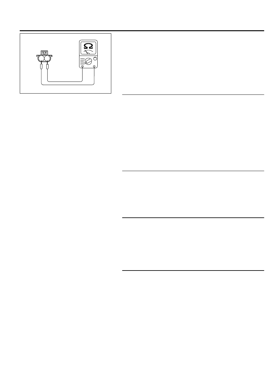
Injector side
connector
1 2
(3)
Measure the resistance between injector side connector
terminal No. 1 and No. 2.
Standard value: 10.5 - 13.5 Ω [at 20 °C (68°F)]
Q:Is the measured resistance between 10.5 and 13.5 ohms
[at 20°C (68°F)]?
YES:
Go to Step 13.
NO:
Replace the injector. Then confirm that the
malfunction symptom is eliminated.
STEP 13. Check harness connector B-101, B-103, B-104 at
right bank injector for damage.
(1)
Check the injector connector, which deviates from the
standard value at Step 11.
Q:Is the harness connector in good condition?
YES:
Repair harness wire between injector intermediate
connector and right bank injector connector because of
harness damage. Then confirm that the malfunction symptom
is eliminated.
NO:
Repair or replace it. Refer to GROUP 00E, Harness
Connector Inspection P.00E-2. Then confirm that the
malfunction symptom is eliminated.
STEP 14. Check harness connector B-21 at intermediate
connector for damage.
Q:Is the harness connector in good condition?
YES:
Go to Step 15.
NO:
Repair or replace it. Refer to GROUP 00E, Harness
Connector Inspection P.00E-2. Then confirm that the
malfunction symptom is eliminated.
STEP 15. Check harness connector B-10 at ECM and
harness connector B-115, B-116, B-120 at left bank injector
for damage.
Q:Is the harness connector in good condition?
YES:
Go to Step 16.
NO:
Repair or replace it. Refer to GROUP 00E, Harness
Connector Inspection P.00E-2. Then confirm that the
malfunction symptom is eliminated.
STEP 16. Check for harness damage between injector
connector and ECM connector.
(1)
Disconnect the injector connector and ECM connector.
MULTIPORT INJECTION SYSTEM (MFI) <DIAGNOSIS>
13Ab-763
SYMPTOM PROCEDURES