Mitsubishi Outlander XL. Manual - part 386
STEP 1. Replace the DOR radiator.
ZC501967
AC404789
ZC501968
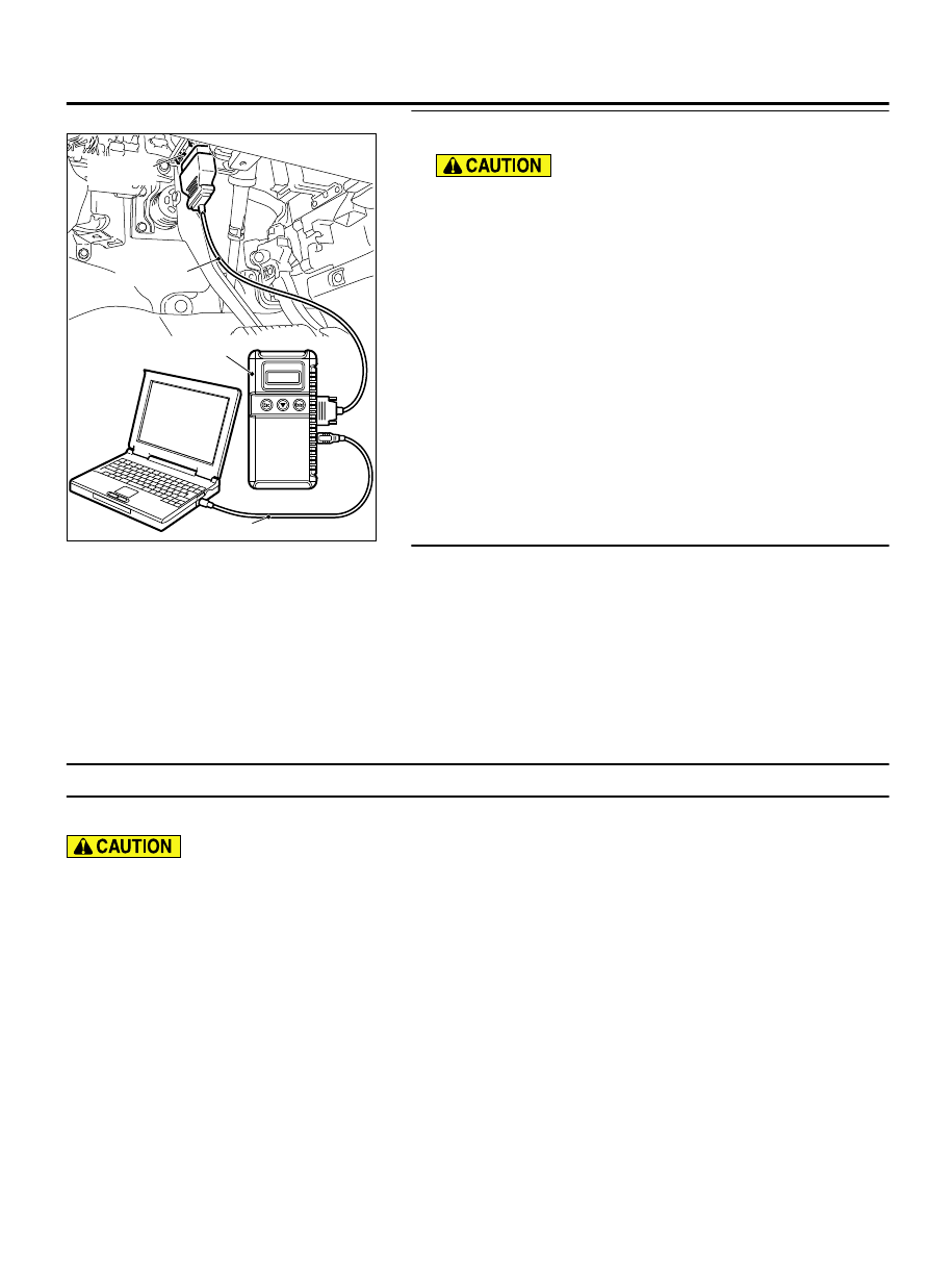
MB991824
MB991827
MB991910
Data link
connector
AA00
(1)
Replace the DOR radiator.
To prevent damage to scan tool MB991958, always turn
the ignition switch to the "LOCK" (OFF) position before
connecting or disconnecting scan tool MB991958.
(2)
Connect scan tool MB991958 to the data link connector.
(3)
Turn the ignition switch to the "ON" position.
(4)
Read the DTC.
(5)
Turn the ignition switch to the "LOCK" (OFF) position.
Q:Is DTC P2567 set?
YES:
Replace the ECM. When the ECM is replaced, register
the ID code. Refer to GROUP 42B, ID Code Registration
Judgment Table <Vehicles with KOS> P.42B-12or GROUP
42C, ID Code Registration Judgment Table <Vehicles with
WCM> P.42C-8. Then go to Step 2.
NO:
It can be assumed that this malfunction is
intermittent. Refer to GROUP 00, How to Use
Troubleshooting/Inspection Service Points - How to Cope
with Intermittent Malfunctions P.00-15.
STEP 2. Using scan tool MB991958, read the diagnostic
trouble code (DTC).
(1)
Turn the ignition switch to the "ON" position.
(2)
Read the DTC.
(3)
Turn the ignition switch to the "LOCK" (OFF) position.
Q:Is DTC P2567 set?
YES:
Repeat the troubleshooting.
NO:
The procedure is complete.
DTC U0001: Bus Off
M11310100397USA0000010000
⦆
If the ECM output the DTC U0001, make sure to
diagnose the CAN bus line.
⦆
Before replacing the ECU, make sure that the
communication circuit is operating normally.
DTC SET CONDITIONS
Check Conditions
⦆
Always
Judgement Criterion
⦆
Bus off error detected
TROUBLESHOOTING HINTS (The most likely
causes for this code to be set are:)
⦆
CAN line harness damage or connector damage.
DIAGNOSIS
Required Special Tools:
⦆
MB991958: Scan tool (M.U.T.-III Sub Assembly)
⦆
MB991824: V.C.I.
MULTIPORT INJECTION SYSTEM (MFI) <DIAGNOSIS>
13Ab-739
DIAGNOSTIC TROUBLE CODE PROCEDURES