Mitsubishi Outlander XL. Manual - part 373
DTC SET CONDITIONS
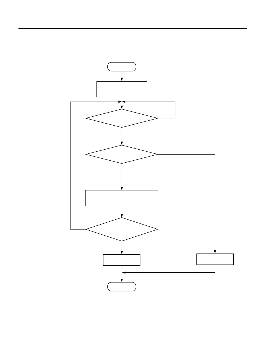
Logic Flow Chart
Indicated
fuel level change
< 2L (0.5gal)
Accumulated fuel consumption
through fuel injectors.
Accumulated fuel
consumption will not
reset when key-off/on.
Accumulated
fuel consumption
> =specified valve
Start
End
No
No
No
Yes
Yes
Yes
Malfunction
Good
Monitoring
conditions
Reset accumulated
fuel consumption.
ZK600946AA00
Check Condition, Judgement Criterion
MULTIPORT INJECTION SYSTEM (MFI) <DIAGNOSIS>
13Ab-687
DIAGNOSTIC TROUBLE CODE PROCEDURES