Mitsubishi Outlander XL. Manual - part 372
ZK603194
82 81 80 79 78 77 76 75 74 73 72 71
94 93 92 91 90 89 88 87 86 85 84 83
99 98 97 96 95
100
101
102
103
104
105
106
112
113
114
109 108
107
110
111
115
116
117
118
AA00
Special tool 48-pin
connector:
component side
(2)
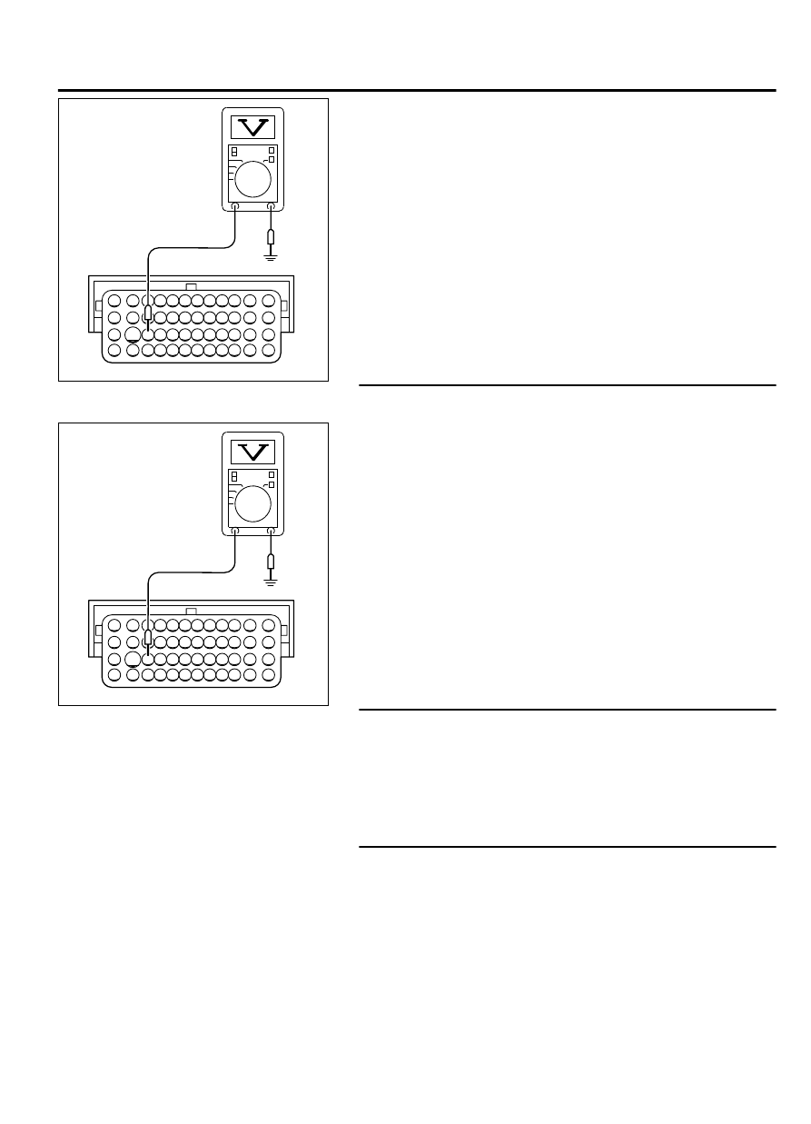
Measure the voltage between terminal No. 104 and ground.
⦆
Voltage should be battery positive voltage.
Q:Is battery positive voltage (approximately 12 volts)
present?
YES:
Go to Step 5.
NO:
Go to Step 3.
STEP 3. Measure the backup power supply voltage at ECM
harness side connector B-11.
ZK603194
82 81 80 79 78 77 76 75 74 73 72 71
94 93 92 91 90 89 88 87 86 85 84 83
99 98 97 96 95
100
101
102
103
104
105
106
112
113
114
109 108
107
110
111
115
116
117
118
AA00
Special tool 48-pin
connector:
component side
(1)
Disconnect the ECM connector B-11 and measure at the
harness side.
(2)
Measure the voltage between terminal No. 104 and ground.
⦆
Voltage should be battery positive voltage.
Q:Is battery positive voltage (approximately 12 volts)
present?
YES:
Go to Step 4.
NO:
Repair harness wire between battery and ECM connector
B-11 (terminal No. 104) because of open circuit or short
circuit to ground. Then go to Step 6.
STEP 4. Check harness connector B-11 at ECM for damage.
Q:Is the harness connector in good condition?
YES:
Repair harness wire between battery and ECM
connector B-11 (terminal No. 104) because of harness
damage. Then go to Step 6.
NO:
Repair or replace it. Refer to GROUP 00E, Harness
Connector Inspection P.00E-2. Then go to Step 6.
STEP 5. Check harness connector B-11 at ECM for damage.
Q:Is the harness connector in good condition?
YES:
Replace the ECM. When the ECM is replaced, register
the ID code. Refer to GROUP 42B, ID Code Registration
Judgment Table <Vehicles with KOS> P.42B-12or GROUP
42C, ID Code Registration Judgment Table <Vehicles with
WCM> P.42C-8. Then go to Step 6.
NO:
Repair or replace it. Refer to GROUP 00E, Harness
Connector Inspection P.00E-2. Then go to Step 6.
MULTIPORT INJECTION SYSTEM (MFI) <DIAGNOSIS>
13Ab-683
DIAGNOSTIC TROUBLE CODE PROCEDURES