Mitsubishi Outlander XL. Manual - part 363
DTC P1241: Torque Monitoring
M11310100387USA0000010000
TECHNICAL DESCRIPTION
Compares the actual torque signal computed from a
mass air flow sensor signal with the driver demand
torque signal computed from an accelerator pedal
position sensor signal.
MONITOR EXECUTION
Continuous
MONITOR EXECUTION CONDITIONS (Other
monitor and Sensor)
Other Monitor (There is no temporary DTC stored in
memory for the item monitored below)
⦆
Not applicable
Sensor (The sensor below is determined to be
normal)
⦆
Not applicable
DTC SET CONDITIONS
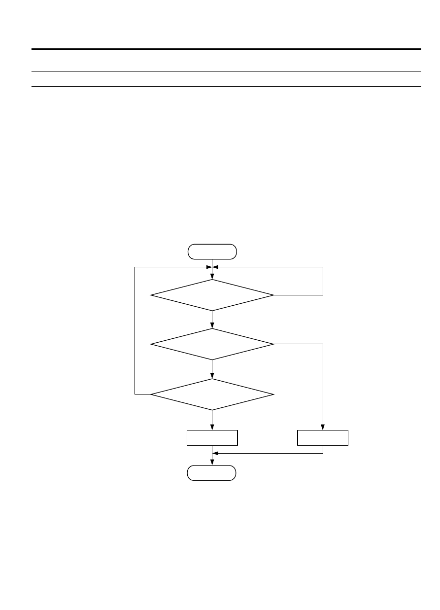
Logic Flow Chart
ZK604067 AA00
Start
End
No
No
Yes
Yes
Yes
No
Malfunction
Good
Continuous
failure for 1sec
Actual torque-permitted
torque > 50Nm
Monitoring
conditions
Check Conditions
⦆
Engine speed is 500 r/min or higher.
⦆
Volumetric efficiency is 16 percent or higher.
MULTIPORT INJECTION SYSTEM (MFI) <DIAGNOSIS>
13Ab-647
DIAGNOSTIC TROUBLE CODE PROCEDURES