Mitsubishi Outlander XL. Manual - part 337
DIAGNOSIS
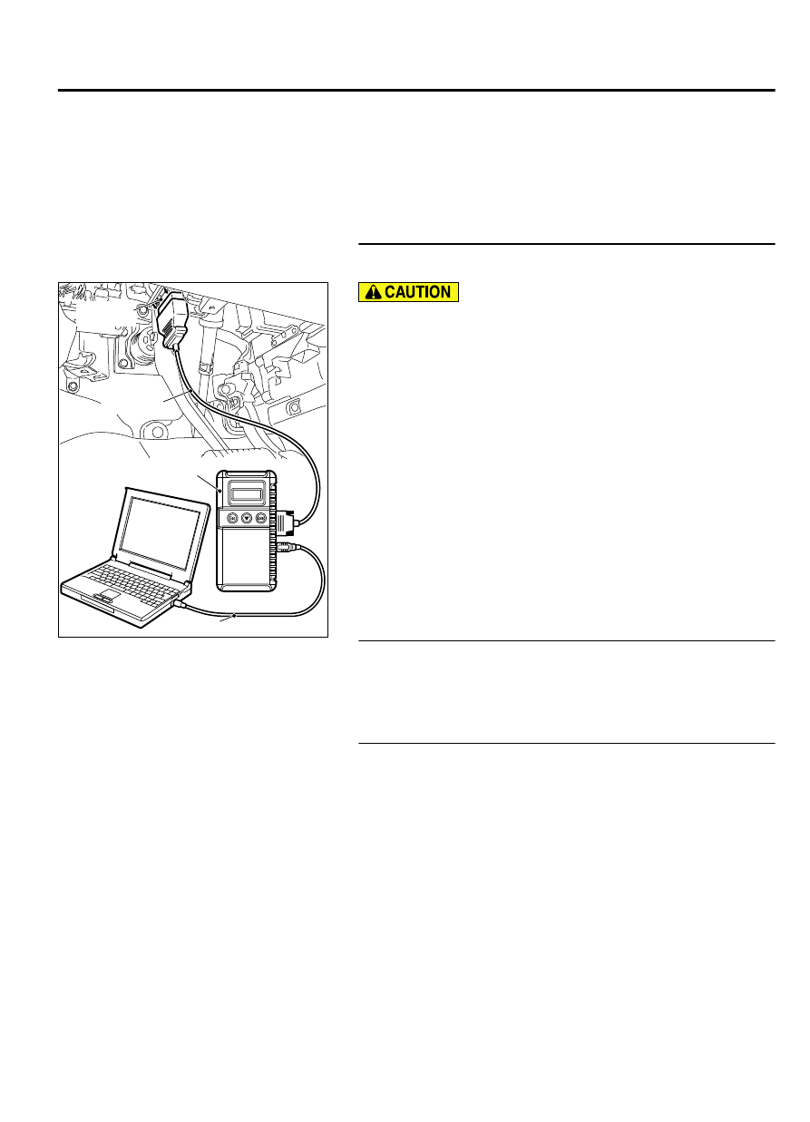
Required Special Tools:
⦆
MB991958: Scan Tool (M.U.T.-III Sub Assembly)
⦆
MB991824: V.C.I.
⦆
MB991827: USB Cable
⦆
MB991910: Main Harness A
STEP 1. Using scan tool MB991958, read the diagnostic
trouble code (DTC).
ZC501967
AC404789
ZC5019680000
MB991824
MB991827
MB991910
Data link
connector
To prevent damage to scan tool MB991958, always turn the
ignition switch to the "LOCK" (OFF) position before
connecting or disconnecting scan tool MB991958.
(1)
Connect scan tool MB991958 to the data link connector.
(2)
Turn the ignition switch to the "ON" position.
(3)
Read the DTC.
(4)
Turn the ignition switch to the "LOCK" (OFF) position.
Q:Is DTC P2066 set?
YES:
Go to Step 2.
NO:
Go to Step 4.
STEP 2. Check fuel gauge.
Q:Is the fuel gauge functioning?
YES:
Go to Step 3.
NO:
Refer to GROUP 54A, Chassis Electrical - Combination
Meters Assembly - Symptom Chart P.13Ab-8.
STEP 3. Check the trouble symptoms.
Check that the fuel gauge operates correctly.
Q:Does the fuel gauge operate correctly?
YES:
It can be assumed that this malfunction is
intermittent. Refer to GROUP 00, How to Use
Troubleshooting/Inspection Service Points - How to Cope
with Intermittent Malfunctions P.00-15.
NO:
Replace the ECM. When the ECM is replaced, register
the ID code. Refer to GROUP 42B, ID Code Registration
Judgment Table <Vehicles with KOS> P.42B-12or GROUP
42C, ID Code Registration Judgment Table <Vehicles with
WCM> P.42C-8. Then go to Step 6.
MULTIPORT INJECTION SYSTEM (MFI) <DIAGNOSIS>
13Ab-543
DIAGNOSTIC TROUBLE CODE PROCEDURES