Mitsubishi Outlander XL. Manual - part 298
DIAGNOSIS
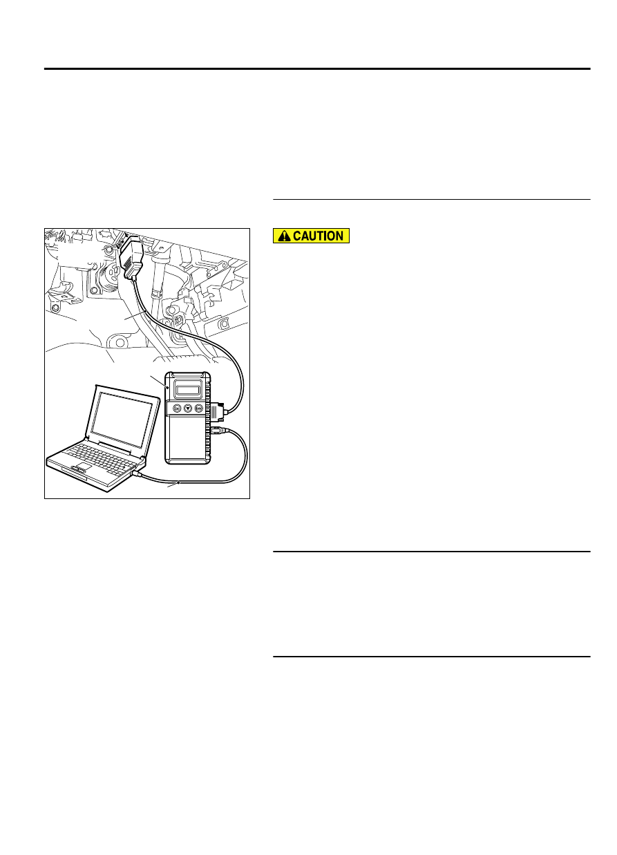
Required Special Tools:
⦆
MB991958: Scan Tool (M.U.T.-III Sub Assembly)
⦆
MB991824: V.C.I.
⦆
MB991827: USB Cable
⦆
MB991910: Main Harness A
⦆
MB991658: Test Harness
STEP 1. Using scan tool MB991958, check data list item 15:
Throttle Position Sensor (sub).
ZC501967
AC404789
ZC5019680000
MB991824
MB991827
MB991910
Data link
connector
To prevent damage to scan tool MB991958, always turn the
ignition switch to the "LOCK" (OFF) position before
connecting or disconnecting scan tool MB991958.
(1)
Connect scan tool MB991958 to the data link connector.
(2)
Turn the ignition switch to the "ON" position.
(3)
Detach the intake air hose at the throttle body.
(4)
Disconnect the connector of the throttle position sensor.
(5)
Use test harness special tool (MB991658) to connect only
terminals No. 3, No. 4, No. 5, and No. 6.
(6)
Set scan tool MB991958 to the data reading mode for item
15, Throttle Position Sensor (sub).
⦆
Output voltage should be 4.0 volts or more when the
throttle valve is fully closed with your finger.
⦆
Output voltage should be 1.0 volt or less when the throttle
valve is fully open with your finger.
(7)
Turn the ignition switch to the "LOCK" (OFF) position.
Q:Is the sensor operating properly?
YES:
It can be assumed that this malfunction is
intermittent. Refer to GROUP 00, How to Use
Troubleshooting/Inspection Service Points - How to Cope
with Intermittent Malfunctions P.00-15.
NO:
Go to Step 2.
STEP 2. Check harness connector B-08 at the throttle
position sensor and harness connector B-10 at the ECM for
damage.
Q:Is the harness connector in good condition?
YES:
Go to Step 3.
NO:
Repair it. Refer to GROUP 00E, Harness Connector
Inspection P.00E-2. Then go to Step 6.
STEP 3. Check for open circuit and harness damage
between the throttle position sensor connector B-08 and
ECM connector B-10.
(1)
Disconnect the throttle position sensor connector B-08 and
the ECM connector B-10.
MULTIPORT INJECTION SYSTEM (MFI) <DIAGNOSIS>
13Ab-387
DIAGNOSTIC TROUBLE CODE PROCEDURES