Mitsubishi Outlander XL. Manual - part 296
DTC SET CONDITIONS
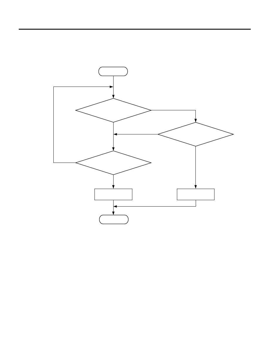
Logic Flow Chart
Start
Yes
Yes
Yes
No
No
No
Continuous
failure for 0.3sec
Malfunction
End
Good
Output voltage <= 0.2V
(main), 0.2V (sub)
Output voltage > =4.8V
ZK603749 AA00
Check Condition
⦆
Ignition switch is "ON" position.
Judgement Criterion
⦆
Throttle position sensor (sub) output voltage should
be 0.2 volt or less for 0.3 second.
OBD-II DRIVE CYCLE PATTERN
None.
TROUBLESHOOTING HINTS (The most likely
causes for this code to be set are:)
⦆
Throttle position sensor failed.
⦆
Connector damage
⦆
Harness damage
⦆
ECM failed.
MULTIPORT INJECTION SYSTEM (MFI) <DIAGNOSIS>
13Ab-379
DIAGNOSTIC TROUBLE CODE PROCEDURES