Mitsubishi Outlander XL. Manual - part 265
DTC SET CONDITIONS
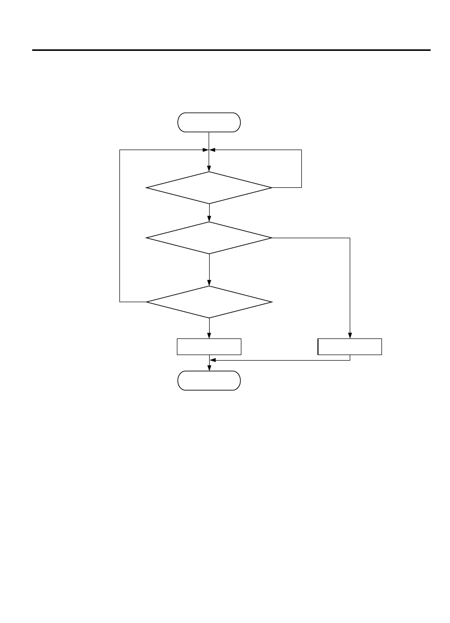
Logic Flow Chart
End
Malfunction
Yes
Yes
Yes
No
No
No
2secs have passed?
Output voltage
< 0.2V
Monitoring
conditions
Good
Start
ZK603708 AA00
Check Conditions
⦆
Heated oxygen sensor offset voltage is between 0.4
and 0.6 volt.
⦆
Battery positive voltage is between 11 and 16.5
volts.
⦆
Typically 60 seconds have passed since the engine
starting sequence was completed.
Judgement Criterion
⦆
Left bank heated oxygen sensor (front) output
voltage is lower than 0.2 volts.
OBD-II DRIVE CYCLE PATTERN
Refer to Diagnostic Function - OBD-II Drive Cycle -
Pattern 23 P.13Ab-8.
TROUBLESHOOTING HINTS (The most likely
causes for this code to be set are:)
⦆
Left bank heated oxygen sensor (front) failed.
⦆
Connector damage.
⦆
Harness damage.
⦆
ECM failed.
MULTIPORT INJECTION SYSTEM (MFI) <DIAGNOSIS>
13Ab-255
DIAGNOSTIC TROUBLE CODE PROCEDURES