Mitsubishi Outlander XL. Manual - part 253
ZK603590AA00
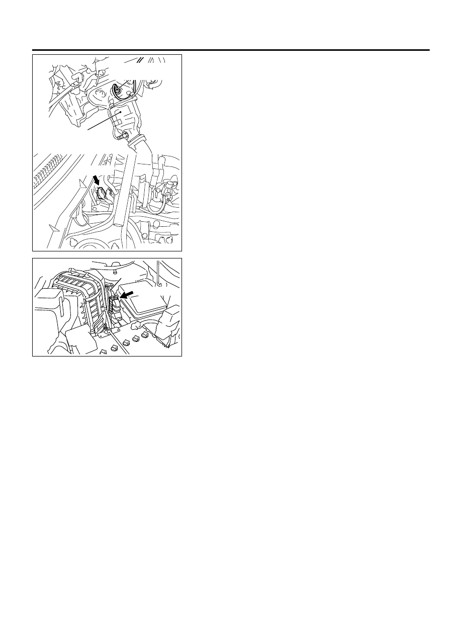
Right bank heated
oxygen sensor (front)
Front exhaust
pipe RH
B-03 (GR)
Connector: B-03
ZK603591
ECM
B-10 (GR)
Connector: B-10
AA00
CIRCUIT OPERATION
⦆
A voltage corresponding to the oxygen
concentration in the exhaust gas is sent to the ECM
(terminal No. 54) from the output terminal (terminal
No. 4) of the right bank heated oxygen sensor
(front).
⦆
Terminal No. 2 of the right bank heated oxygen
sensor (front) is grounded with ECM (terminal No.
55).
⦆
The ECM applies an off set voltage of 0.5 volt to
terminal No. 2 of the right bank oxygen sensor
(front).
TECHNICAL DESCRIPTION
⦆
The right bank heated oxygen sensor (front) detects
the concentration of oxygen in the exhaust gas; it
converts those data to voltage, and inputs the
resulting signals to the ECM.
⦆
When the right bank heated oxygen sensor (front)
begins to deteriorate, the heated oxygen sensor
signal response becomes poor.
⦆
The ECM also checks for the right bank heated
oxygen sensor (front) rich learn switching
frequency.
DESCRIPTIONS OF MONITOR METHODS
Right bank heated oxygen sensor (front) rich/lean
switching frequency is under specified value.
MONITOR EXECUTION
Continuous
MULTIPORT INJECTION SYSTEM (MFI) <DIAGNOSIS>
13Ab-207
DIAGNOSTIC TROUBLE CODE PROCEDURES