Mitsubishi Outlander XL. Manual - part 218
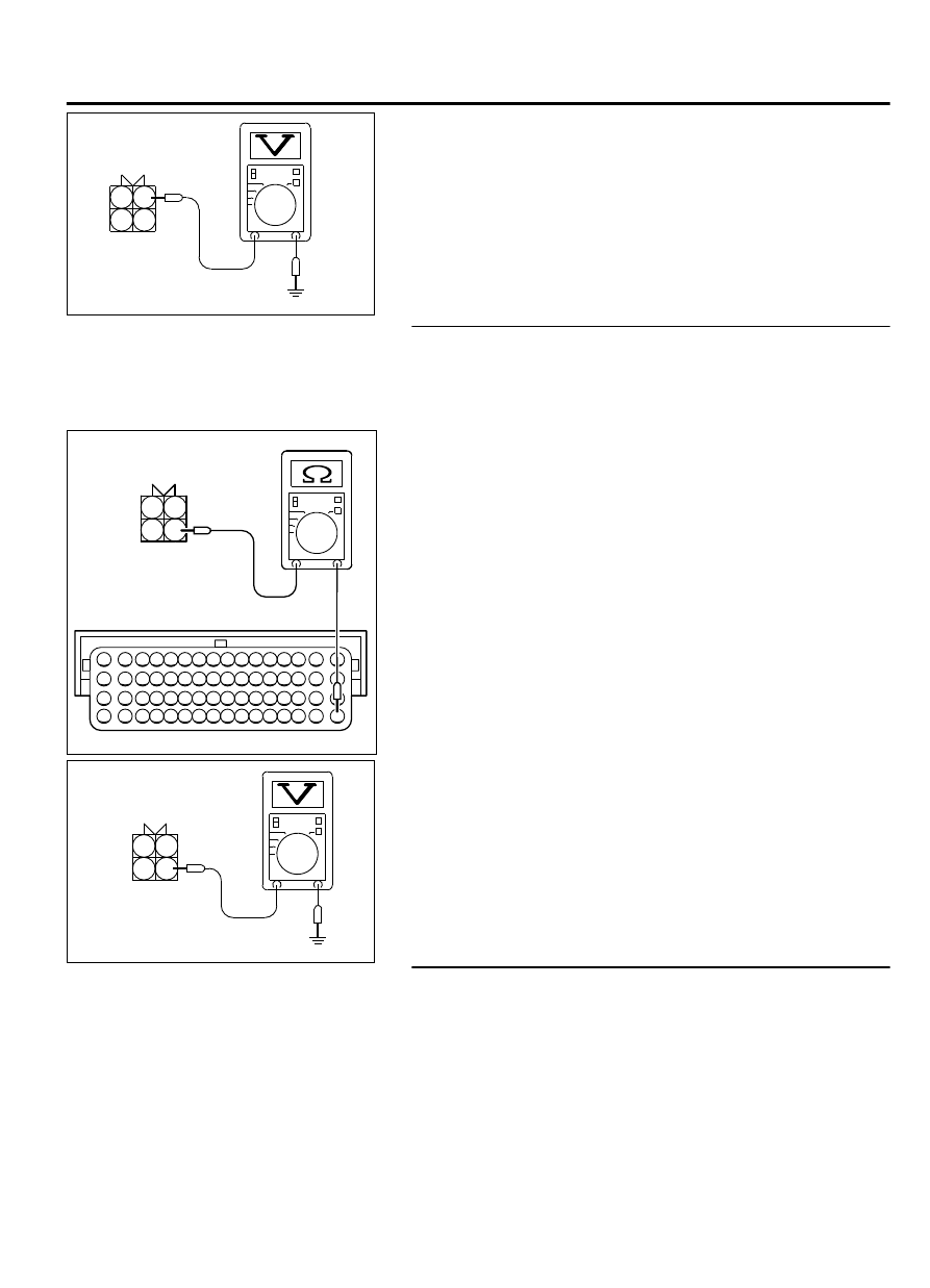
B-02 harness
connector:
component side
1
2
3
4
ZK603155AA00
(3)
Measure the voltage between terminal No. 1 and ground.
⦆
Voltage should be battery positive voltage.
(4)
Turn the ignition switch to the "LOCK" (OFF) position.
Q:Is battery positive voltage (approximately 12 volts)
present?
YES:
Go to Step 4.
NO:
Repair harness wire between the MFI relay connector
A-33X (terminal No. 2) and the right bank heated oxygen
sensor (rear) connector B-02 (terminal No. 1) because of
open circuit or harness damage. Then go to step 6.
STEP 4.Check for open circuit to ground or harness damage
between right bank heated oxygen sensor (rear) connector
B-02 and ECM connector B-10.
(1)
Disconnect the right bank heated oxygen sensor (rear)
connector B-02 and the ECM connector B-10.
ZK603156
1
2
3
4
16 15 14 13 12 11 10 9 8 7 6 5 4 3
2
1
32 31 30 29 28 27 26 25 24 23 22 21 20 19 18 17
48 47 46 45 44 43 42 41 40 39 38 37 36 35 34 33
64 63 62 61 60 59 58 57 56 55 54 53 52 51 50 49
B-02 harness connector:
component side
B-10 harness connector:
component side
AA00
(2)
Measure the resistance between the heated oxygen sensor
connector B-02 (terminal No. 3) and ECM connector B-10
(terminal No. 49).
⦆
Should be less than 2 ohms.
ZK603157AA00
B-02 harness
connector:
component side
1
2
3
4
(3)
Check for the continuity between the oxygen sensor
connector B-02 (terminal No. 3) and ground.
⦆
Not continuity.
Q:Is the harness wire in good condition?
YES:
Go to Step 5.
NO:
Repair it. Then go to Step 6.
STEP 5. Check the trouble symptoms.
(1)
Carry out a test drive with the drive cycle pattern. Refer to
Diagnostic Function - OBD-II Drive Cycle - Pattern 2 P.
13Ab-8.
(2)
Check the diagnostic trouble code (DTC).
Q:Is DTC P0037 set?
YES:
Replace the ECM. When the ECM is replaced, register
the ID code. Refer to GROUP 42B, ID Code Registration
Judgment Table <Vehicles with KOS> P.42B-12or GROUP
MULTIPORT INJECTION SYSTEM (MFI) <DIAGNOSIS>
13Ab-67
DIAGNOSTIC TROUBLE CODE PROCEDURES