Mitsubishi Outlander XL. Manual - part 217


  Index      Mitsubishi     Mitsubishi Outlander XL - service repair manual 2007 year


Search            


Content   ..  215  216  217  218   ..


Mitsubishi Outlander XL. Manual - part 217


Q:Is DTC P0032 set?

YES:

 Retry the troubleshooting.

NO:

 The inspection is complete.

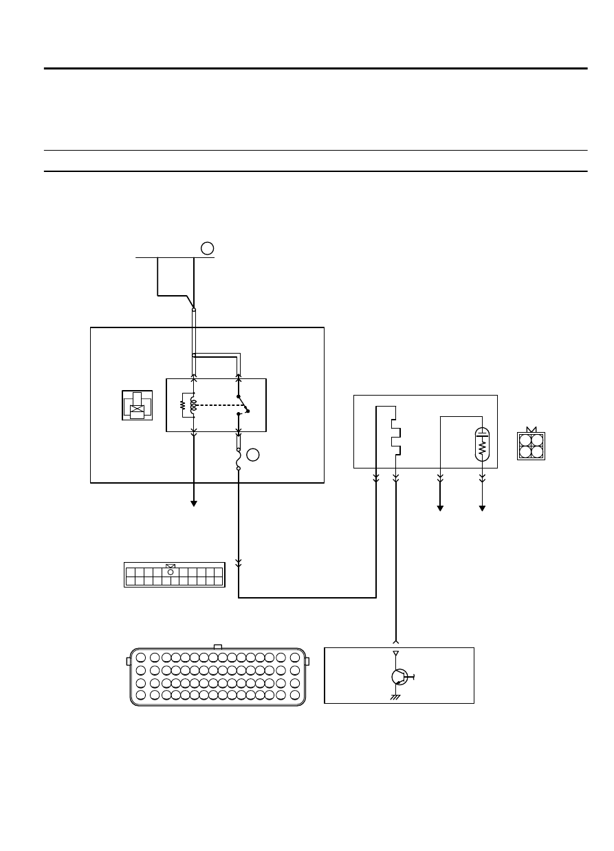
DTC P0037: Heated Oxygen Sensor Heater Control Circuit Low (bank 1, sensor 2)

M11310100163USA0000010000

ZK602829

1

3

2

4

1

2

3 4 5 6 7 8 9 10 11 12 13 14 15 16

17 18 19 20 21 22 23 24 25 26 27 28 29 30 31 32

33 34 35 36 37 38 39 40 41 42 43 44 45 46 47 48

49 50 51 52 53 54 55 56 57 58 59 60 61 62 63 64

1

10 111213 14 1516 17 1819 20

2 3 4

5 6 7 8 9

2

1

4

3

AA00

RIGHT BANK HEATED OXYGEN SENSOR (REAR) HEATER CIRCUIT

20A

WHITE

BLUE-WHITE

WHITE

WHITE

WHITE

A-33X

MFI
RELAY

RELAY BOX
(ENGINE COMPARTMENT)

4

3

1

2

22

TO ECM

RIGHT BANK HEATED
OXYGEN SENSOR (REAR)

1

2

3

4

TO ECM TO ECM

ENGINE
CONTROL
MODULE

49

4

B-02

MU802605

B-10

A-13

OFF

ON

36

FUSIBLE LINK

MULTIPORT INJECTION SYSTEM (MFI) <DIAGNOSIS>

13Ab-63

DIAGNOSTIC TROUBLE CODE PROCEDURES

ZK603589

MFI relay

A-33X

Connector: A-33X

AA00

ZK603593AA00

Right bank heated
oxygen sensor (rear)

Front exhaust 
pipe RH

B-02 (B)

Connector: B-02

ZK603591

ECM

B-10 (GR)

Connector: B-10

AA00

ZK603650AA00

A-13

Connector: A-13


CIRCUIT OPERATION

Power is supplied from the MFI relay (terminal No.
4)  to  the  right  bank  heated  oxygen  sensor  (rear)
heater.

The ECM (terminal No. 49) controls continuity to the
right bank heated oxygen sensor (rear) heater by
turning the power transistor in the ECM "ON" and
"OFF".

TECHNICAL DESCRIPTION

The  ECM  checks  whether  the  heater  current  is
within  a  specified  range  when  the  heater  is
energized.

The  ECM  checks  whether  the  heater  voltage  is
within  a  specified  range  when  the  heater  is  not
energized.

DESCRIPTIONS OF MONITOR METHODS

Right  bank  heated  oxygen  sensor  heater  (rear)
current or voltage is out of specified range.

MONITOR EXECUTION

Continuous

MONITOR EXECUTION CONDITIONS (Other
monitor and Sensor)

Other Monitor (There is no temporary DTC stored in
memory for the item monitored below)

Not applicable

Sensor (The sensor below is determined to be
normal)

Not applicable

13Ab-64

MULTIPORT INJECTION SYSTEM (MFI) <DIAGNOSIS>

DIAGNOSTIC TROUBLE CODE PROCEDURES

DTC SET CONDITION

Logic Flow Chart

Start

End

Yes

Yes

Yes

No

No

No

Malfunction

Good

Continuous

failure for 2secs

Monitoring

conditions

Current < 0.17A

or

Current > 10.5A

Voltage < 2.0V

ZK603657 AA00

Heater ON

Yes

Yes

No

Check Conditions

More than 2 seconds have passed since the engine
starting sequence was completed.

While the right bank heated oxygen sensor (rear)
heater is on.

Battery positive voltage is at between 11 and 16.5
volts.

Judgement Criterion

The right bank heated oxygen sensor (rear) heater
current has continued to be lower than 0.17 ampere
for 2 seconds.

Check Conditions

More than 2 seconds have passed since the engine
starting sequence was completed.

While the right bank heated oxygen sensor (rear)
heater is off.

Battery positive voltage is at between 11 and 16.5
volts.

Judgement Criterion

The right bank heated oxygen sensor (rear) heater
voltage has continued to be lower than 2.0 voltage
for 2 seconds.

MULTIPORT INJECTION SYSTEM (MFI) <DIAGNOSIS>

13Ab-65

DIAGNOSTIC TROUBLE CODE PROCEDURES

OBD-II DRIVE CYCLE PATTERN

Refer to Diagnostic Function - OBD-II Drive Cycle -
Pattern 2 P.13Ab-8.

TROUBLESHOOTING HINTS (The most likely
causes for this code to be set are: )

Right  bank  heated  oxygen  sensor  (rear)  heater
failed.

Connector damage.

Harness damage

ECM failed.


DIAGNOSIS

Required Special Tools:

MB998464: Test Harness

STEP 1. Check harness connector B-02 at the right bank
heated oxygen sensor (rear) and harness connector B-10 at
the ECM for damage.

Q:Is the harness connector in good condition?

YES:

 Go to Step 2.

NO:

 Repair or replace it. Refer to GROUP 00E, Harness

Connector Inspection P.00E-2. Then go to Step 6.

STEP 2. Check the right bank heated oxygen sensor (rear).

ZK603154

Heated
oxygen
sensor
component
side
connector

MD998464

Red

Blue

AA00

(1)

Disconnect  the  right  bank  heated  oxygen  sensor  (rear)
connector  B-02  and  connect  test  harness  special  tool,
MD998464, to the connector on the right bank heated oxygen
(rear) sensor side.

(2)

Measure  the  resistance  between  heated  oxygen  sensor
connector terminal No. 1 (red clip) and terminal No. 3 (blue
clip).

Standard value: 11 - 18 Ω [at 20°C (68°F)]

Q:Is the measured resistance between 11 and 18 ohms [at

20°C (68°F)]?

YES:

 Go to Step 3.

NO:

 Replace the right bank heated oxygen sensor (rear).

Then go to Step 6.

STEP 3. Measure the power supply voltage at right bank
heated oxygen sensor (rear) and harness side connector
B-02.

(1)

Disconnect the connector B-02 and measure at the harness
side.

(2)

Turn the ignition switch to the "ON" position.

13Ab-66

MULTIPORT INJECTION SYSTEM (MFI) <DIAGNOSIS>

DIAGNOSTIC TROUBLE CODE PROCEDURES


Content   ..  215  216  217  218   ..