Mitsubishi Outlander XL. Manual - part 157
DRIVE BELT TENSION CHECK AND
ADJUSTMENT
M11102000906USA0000010000
POWER STEERING OIL PUMP DRIVE BELT
TENSION CHECK
WHEN USING SPECIAL TOOL MB992080:
RECOMMENDATION
Required Special Tools:
⦆
MB992080: Belt tension meter set
⦆
MB992081: Belt tension meter
⦆
MB992082: Microphone assembly
NOTE:
The vibration frequency measuring method is
recommended for check and adjustment of the drive belt
tension.
ZC5012270000
MB992081
Belt tension meter set (MB992080)
MB992082
1.
Connect the special tool MB992082 to the special tool
MB992081 of the Special tool MB992080.
2.
Press the "POWER" button to turn on the power supply.
3.
Press the numeral key of "1" and check that "No.1" appears
on the upper left of the display.
NOTE:
This operation is to temporarily set the preset
data such as the belt specifications, because if the
measurement is taken without input of the belt
specifications, conversion to tension value (N) cannot be
made, resulting in judgement of error.
4.
Press "Hz" button twice to change the display to the frequency
display (Hz).
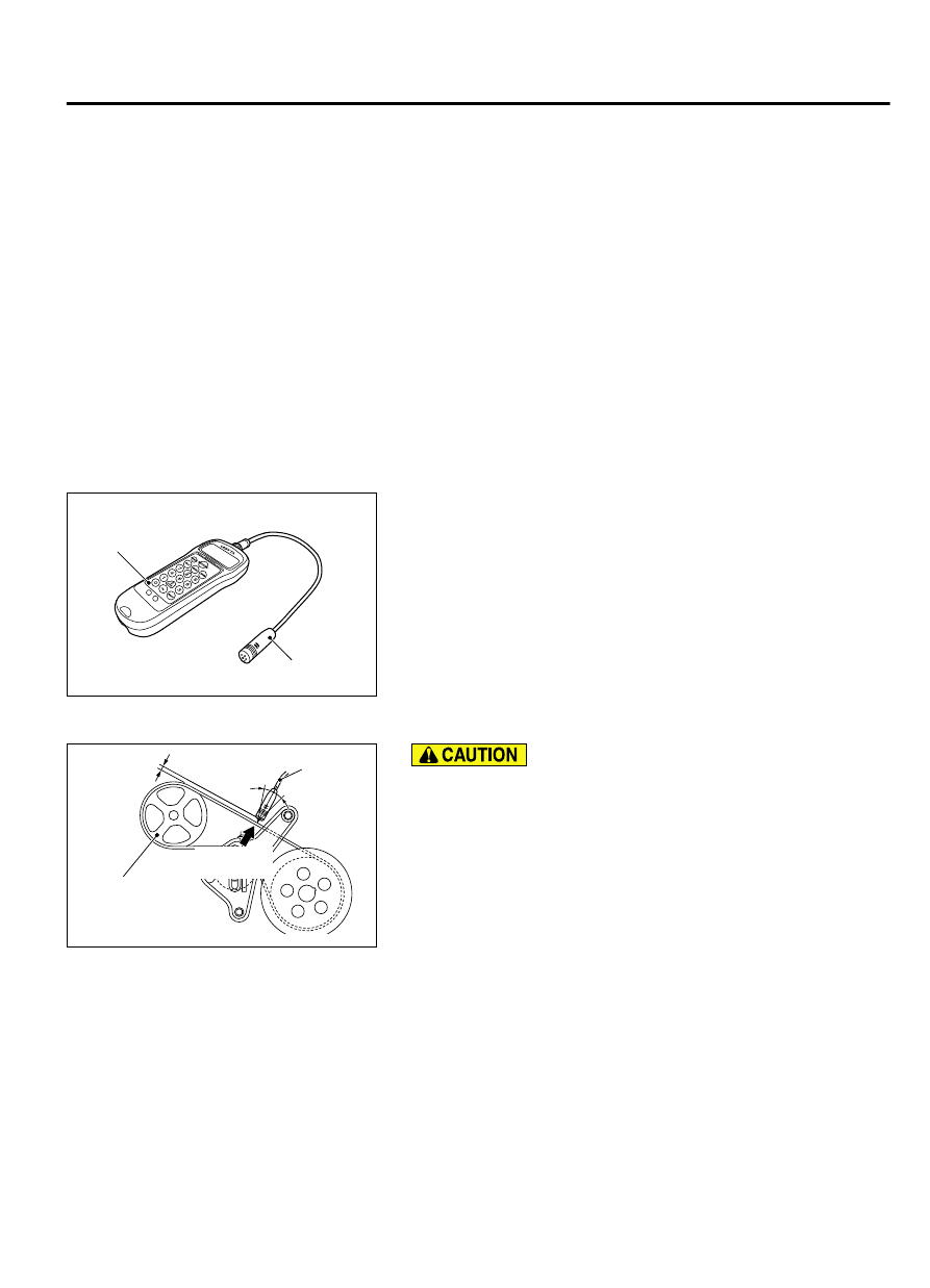
ZC600450
15˚
15˚
10 − 15 mm
(0.4 − 0.59 in)
MB992080
Tap lightly
with a finger
Power steering
oil pump pulley
AA00
⦆
The temperature of the surface of the belt should be as
close to normal temperature as possible.
⦆
Do not allow any contaminants such as water or oil to get
onto the microphone.
⦆
If strong gusts of wind blow against the microphone or if
there are any loud sources of noise nearby, the values
measured by the microphone may not correspond to
actual values.
⦆
If the microphone is touching the belt while the
measurement is being made, the values measured by the
microphone may not correspond to actual values.
⦆
Do not take the measurement while the vehicle's engine
is running.
5.
Hold special tool MB992080 to the middle of the drive belt
between the pulleys (at the place indicated by arrow),
approximately 10 - 15 mm (0.4 - 0.59 inch) away from the rear
surface of the belt so that it is perpendicular to the belt (within
an angle of ± 15 degree).
6.
Press the "MEASURE" button.
ENGINE MECHANICAL
11A-9
ON-VEHICLE SERVICE