Content .. 1330 1331 1332 1333 ..
Mitsubishi Outlander XL. Manual - part 1332
ZC600495
A C115V100
W
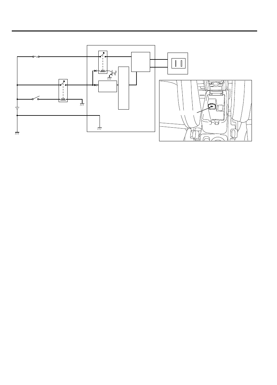
IG1 relay
IG1 swith
(IG1)
AC inverter
AC outlet
C
P
U
AC outlet
0000
Power
circuit
Inverter
parts
⦆
With the AC inverter, the DC power supply of the
vehicle battery can be inverted into the AC power
supply and provided from the AC outlet.
⦆
The electric appliance whose power consumption is
100 W or less when 115 V AC is supplied can be
used.
NOTE:
The home appliance whose power
consumption is 100 W or less but requires a
large amount of power at startup (such as TV,
refrigerator, vacuum cleaner) may not be used.
⦆
To prevent damage caused by overcurrent,
overvoltage, low voltage, and overheat* when the
power is supplied, there is a protection function to
stop the power supply and prevention function
against dead battery.
NOTE:
*: When the inside of the vehicle is held
at high temperatures (35°C or more) for a long
time (for example under the scorching sun), if
the AC power supply is used with the vehicle
parked, the operation may automatically stop to
prevent the inverter unit from being
overheated.After the power supply is cut off,
when the AC inverter temperature decreases, the
power automatically returns to ON.
⦆
When the power supply stops, turn the ignition
switch to "LOCK" (OFF) position once to inhibit the
power supply to the AC inverter. After that, turn the
ignition switch to "ON" again for return.
HANDS FREE CELLULAR PHONE SYSTEM
GENERAL INFORMATION
M25400000001USA0000010011
With the hands-free cellular phone system, by
registering a cellular phone for Bluetooth™*with voice
recognition to the hands free module, the telephone
function becomes available without operating the
cellular phone directly. The hands-free cellular phone
system can be used without connecting the cellular
phone to the vehicle via wiring cable.
NOTE:
*: Bluetooth™ is the short-distance
digital wireless communication technology using
2.45 GHz frequency band. The communication
effective area is within 10 m, and the feature is
that the communication can be achieved even when
an obstacle is present between the communicating
devices.
54A-26
CHASSIS ELECTRICAL
ACCESSORY