Mitsubishi Outlander XL. Manual - part 1186


  Index      Mitsubishi     Mitsubishi Outlander XL - service repair manual 2007 year


Search            


Content   ..  1184  1185  1186  1187   ..


Mitsubishi Outlander XL. Manual - part 1186


STEP 5. Recheck for diagnostic trouble code.
Recheck if the DTC is set.

(1)

Erase the DTC.

(2)

Turn the ignition switch to "ON" position.

(3)

Check if the DTC is set.

Q:Is the check result satisfactory?

YES:

 It can be assumed that this malfunction is

intermittent. Refer to GROUP 00, How to Use
Troubleshooting/Inspection Service Points - How to Cope
with Intermittent Malfunctions P.00-15.

NO:

 Replace the A/C control panel. Then go to Step 6.

STEP 6. Recheck for diagnostic trouble code.
Recheck if the DTC is set.

(1)

Erase the DTC.

(2)

Turn the ignition switch to "ON" position.

(3)

Check if the DTC is set.

Q:Is the check result satisfactory?

YES:

 It can be assumed that this malfunction is

intermittent. Refer to GROUP 00, How to Use
Troubleshooting/Inspection Service Points - How to Cope
with Intermittent Malfunctions P.00-15.

NO:

 Replace the A/C-ECU.

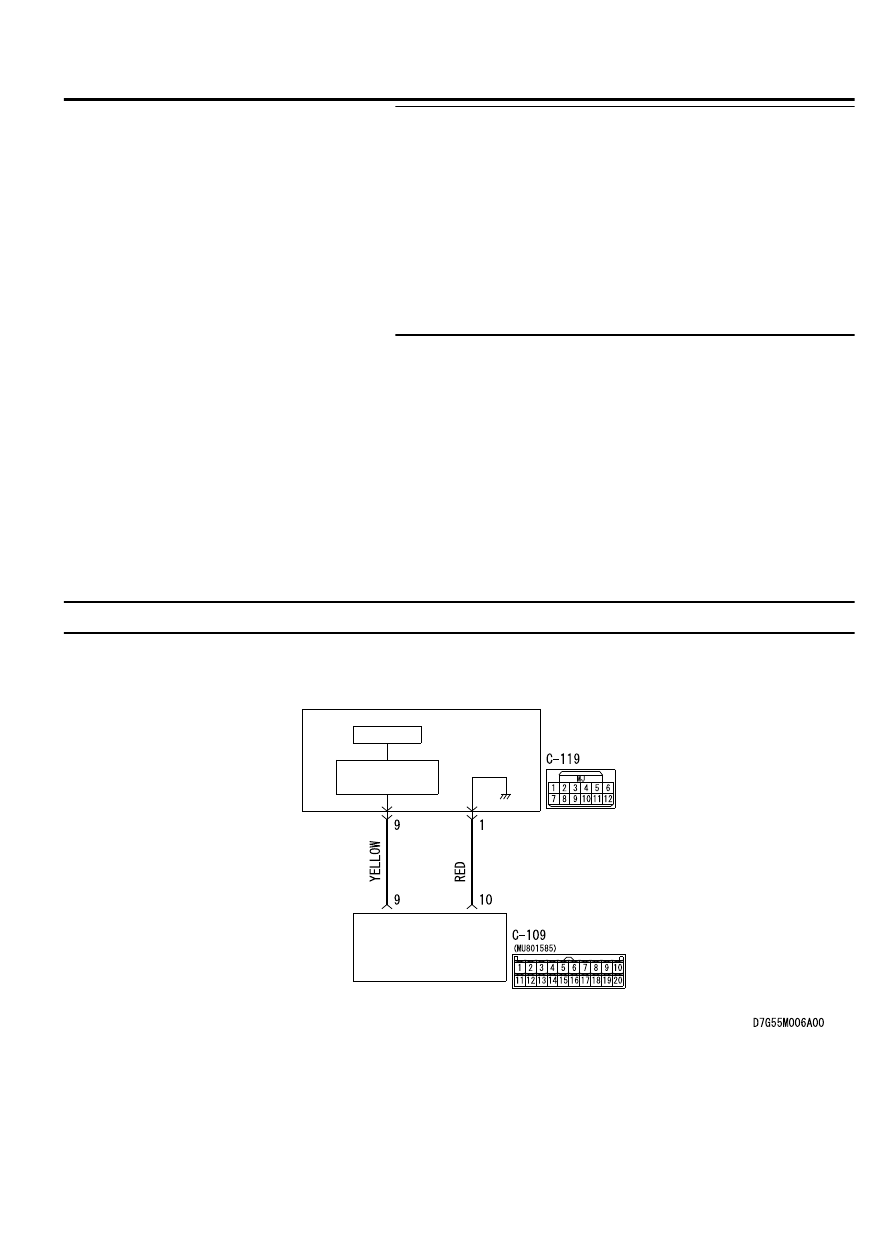
DTC B223B: Control Panel Improperly Assembled

M15502000946USA0000010000

A/C Control Panel Circuit

A/C-ECU

A/C
CONTROL
PANEL

CPU

INTERFACE
CIRCUIT

AIR CONDITIONING

55A-35

MANUAL A/C DIAGNOSIS

ZC600876

Connector: C-109, C-119

C-119

C-109 (B) 

0034


DTC SET CONDITION
DTC  B223B  will  be  set  when  the  A/C  control  panel
sends  an  abnormal  data,  the  A/C  control  panel  for
RHD  is  improperly  assembled,  or  the  ETACS-ECU
sends  incorrect  vehicle  information  (information  for
RHD is sent).

TECHNICAL DESCRIPTION (COMMENT)

Current trouble

The A/C-ECU, the A/C control panel, or connector
(s) or wiring between the two may be defective.

Past trouble

If DTC B223B is stored as a past trouble, carry out
diagnosis  with  particular  emphasis  on  wiring  and
connector(s)  between  the  A/C-ECU  and  the  A/C
control  panel.  If  the  connectors  and  wiring  are
normal, and obviously the ECU is the cause of the
trouble, replace the ECU. If in doubt, do not replace
the ECU.

TROUBLESHOOTING HINT

Malfunction of connector.

Malfunction of the harness.

Malfunction of the A/C control panel.

Malfunction of the A/C-ECU.

DIAGNOSIS

Required Special Tool:

MB991958: Scan Tool (M.U.T.-III Sub Assembly)

MB991824: Vehicle Communication Interface (V.C.I.)

MB991827: M.U.T.-III USB Cable

MB991910:  M.U.T.-III  Main  Harness  A  (Vehicles  with
CAN communication system)

55A-36

AIR CONDITIONING

MANUAL A/C DIAGNOSIS

STEP 1. Using scan tool MB991958, diagnose the CAN bus
line

ZC501967

AC404789

ZC5019680000

MB991824

MB991827

MB991910

Data link

connector

To prevent damage to scan tool MB991958, always turn the
ignition  switch  to  the  "LOCK"  (OFF)  position  before
connecting or disconnecting scan tool MB991958.

(1)

Connect scan tool MB991958. Refer to "How to connect the
Scan Tool (M.U.T.-III) P.55A-6."

(2)

Turn the ignition switch to the "ON" position.

(3)

Diagnose the CAN bus line.

(4)

Turn the ignition switch to the "LOCK" (OFF) position.

Q:Is the CAN bus line found to be normal?

YES:

 Go to Step 2.

NO:

 Repair the CAN bus line. (Refer to GROUP 54D,

Diagnosis P.54D-17).

STEP 2. Recheck for diagnostic trouble code.
Recheck if the DTC is set.

(1)

Erase the DTC.

(2)

Turn the ignition switch to "ON" position.

(3)

Check if the DTC is set.

Q:Is the check result satisfactory?

YES:

 It can be assumed that this malfunction is

intermittent. Refer to GROUP 00, How to Use
Troubleshooting/Inspection Service Points - How to Cope
with Intermittent Malfunctions P.00-15.

NO:

 Go to Step 3.

STEP 3. Check A/C control panel connector C-119 and A/C-
ECU connector C-109 for loose, corroded or damaged
terminals, or terminals pushed back in the connector.

Q:Are  A/C  control  panel  connector  C-119  and  A/C-ECU

connector C-109 in good condition?

YES:

 Go to Step 4.

NO:

 Repair or replace the connector. Refer to GROUP 00E,

Harness Connector Inspection P.00E-2.

STEP 4. Check the wiring harness between A/C-ECU
connector C-109 (terminal 9 and 10) and A/C control panel
connector C-119 (terminals 9 and 1).

Q:Is the wiring harness between A/C-ECU connector C-109

(terminal 9 and 10) and A/C control panel connector C-119

(terminals 9 and 1) in good condition?

YES:

 Go to Step 5.

NO:

 Repair the wiring harness.

AIR CONDITIONING

55A-37

MANUAL A/C DIAGNOSIS

STEP 5. Recheck for diagnostic trouble code.
Recheck if the DTC is set.

(1)

Erase the DTC.

(2)

Turn the ignition switch to "ON" position.

(3)

Check if the DTC is set.

Q:Is the check result satisfactory?

YES:

 It can be assumed that this malfunction is

intermittent. Refer to GROUP 00, How to Use
Troubleshooting/Inspection Service Points - How to Cope
with Intermittent Malfunctions P.00-15.

NO:

 Replace the A/C control panel. Then go to Step 6.

STEP 6. Recheck for diagnostic trouble code.
Recheck if the DTC is set.

(1)

Erase the DTC.

(2)

Turn the ignition switch to "ON" position.

(3)

Check if the DTC is set.

Q:Is the check result satisfactory?

YES:

 It can be assumed that this malfunction is

intermittent. Refer to GROUP 00, How to Use
Troubleshooting/Inspection Service Points - How to Cope
with Intermittent Malfunctions P.00-15.

NO:

 Replace the A/C-ECU.

DTC B222C: Coding Not Completed

M15502000960USA0000010000

If DTC U222C is set in the A/C-ECU, diagnose the
CAN main bus line.

Whenever  the  ECU  is  replaced,  ensure  that  the
communication circuit is normal.

TROUBLE JUDGMENT
The A/C-ECU receives the vehicle information signals
from  the  ETACS-ECU  via  the  CAN  bus  lines.  If

incorrect global coding data is received or coding data
cannot be received with the ignition switch turned ON
when  the  coding  confirmation  is  completed,  the
diagnostic trouble code B222C is stored.

TROUBLESHOOTING HINTS

Malfunction of the ETACS-ECU

Malfunction of the A/C-ECU

Damaged harness wires and connectors

DIAGNOSIS

Required Special Tools:

MB991223: Harness Set

MB992006: Extra Fine Probe

MB991958: Scan Tool (M.U.T.-III Sub Assembly)

MB991824: V.C.I.

MB991827: M.U.T.-III USB Cable

MB991910: M.U.T.-III Main Harness A

55A-38

AIR CONDITIONING

MANUAL A/C DIAGNOSIS


Content   ..  1184  1185  1186  1187   ..