Content .. 1182 1183 1184 1185 ..
Mitsubishi Outlander XL. Manual - part 1184
DIAGNOSIS
Required Special Tool:
⦆
MB991958: Scan Tool (M.U.T.-III Sub Assembly)
⦆
MB991824: Vehicle Communication Interface (V.C.I.)
⦆
MB991827: M.U.T.-III USB Cable
⦆
MB991910: M.U.T.-III Main Harness A (Vehicles with
CAN communication system)
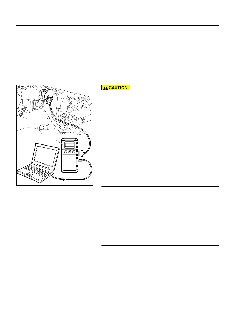
STEP 1. Using scan tool MB991958, diagnose the CAN bus
line
ZC501967
AC404789
ZC5019680000
MB991824
MB991827
MB991910
Data link
connector
To prevent damage to scan tool MB991958, always turn the
ignition switch to the "LOCK" (OFF) position before
connecting or disconnecting scan tool MB991958.
(1)
Connect scan tool MB991958. Refer to "How to connect the
Scan Tool (M.U.T.-III) P.55A-6."
(2)
Turn the ignition switch to the "ON" position.
(3)
Diagnose the CAN bus line.
(4)
Turn the ignition switch to the "LOCK" (OFF) position.
Q:Is the CAN bus line found to be normal?
YES:
Go to Step 2.
NO:
Repair the CAN bus line. (Refer to GROUP 54D,
STEP 2. Recheck for diagnostic trouble code.
Recheck if the DTC is set.
(1)
Erase the DTC.
(2)
Turn the ignition switch to "ON" position.
(3)
Check if the DTC is set.
Q:Is the check result satisfactory?
YES:
It can be assumed that this malfunction is
intermittent. Refer to GROUP 00, How to Use
Troubleshooting/Inspection Service Points - How to Cope
with Intermittent Malfunctions P.00-15.
NO:
Go to Step 3.
STEP 3. Check ambient air temperature sensor connector
A-44 and ETACS-ECU connector C-312 for loose, corroded
or damaged terminals, or terminals pushed back in the
connector.
Q:Are ambient air temperature sensor connector A-44 and
ETACS-ECU connector C-312 in good condition?
YES:
Go to Step 4.
AIR CONDITIONING
55A-27
MANUAL A/C DIAGNOSIS