Content .. 1171 1172 1173 1174 ..
Mitsubishi Outlander XL. Manual - part 1173
ZC5010390016
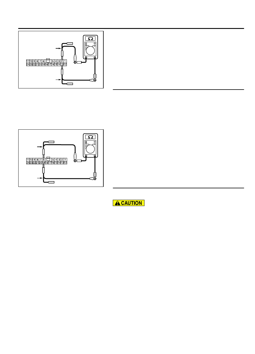
Test harness
Harness side: C-103
Test harness
(2)
Check that there is continuity between joint connector
(CAN1) terminals 2 and 13.
OK: No continuity
Q:Is the check result normal?
YES:
Go to Step 36.
NO:
Go to Step 57.
STEP 36. Check the wiring harness between joint connector
(CAN1) C-103 and EATCS-ECU connector C-301 for line-to-
line short. Measure the resistance at joint connector (CAN1)
C-103.
(1)
Disconnect joint connector (CAN1) and ETACS-ECU
connector C-301, and check that there is continuity at the
harness side of joint connector (CAN1).
ZC5010390017
Test
harness
Harness side: C-103
Test
harness
(2)
Check that there is continuity between joint connector
(CAN1) terminals 6 and 19.
OK: No continuity
Q:Is the check result normal?
YES:
Go to Step 58.
NO:
Repair the wiring harness between joint connector
(CAN1) C-103 and ETACS-ECU connector C-301.
STEP 37. Check the wiring harness between joint connector
(CAN1) C-103 and combination meter connector C-03.
Strictly observe the specified wiring harness repair
procedure. For details refer to P.54D-8.
(1)
Disconnect joint connector (CAN1) C-103 and combination
meter connector C-301, and check the wiring harness.
(2)
Check the wiring harness between joint connector (CAN1)
C-103 (terminal No.6) and combination meter connector
C-03 (terminal No.6)
(3)
Check the wiring harness between joint connector (CAN1)
C-103 (terminal No.14) and combination meter connector
C-03 (terminal No.7)
Q:Is the wiring harness between joint connector (CAN1)
C-103 and combination meter connector C-03 in good
condition?
YES(vehicles with KOS):
Go to Step 38.
YES(vehicles with WCM):
Go to Step 39.
NO((vehicles with KOS or WCM):
Go to Step 48.
CONTROLLER AREA NETWORK (CAN)
54D-175
DIAGNOSIS