Mitsubishi Outlander XL. Manual - part 1172


  Index      Mitsubishi     Mitsubishi Outlander XL - service repair manual 2007 year


Search            


Content   ..  1170  1171  1172  1173   ..


Mitsubishi Outlander XL. Manual - part 1172


ZC5010400040

Harness side: C-103

Test 
harness

(3)

Measure  the  voltage  between  joint  connector  (CAN1)
terminal 6 and body ground.

OK: 4.7 volts or less

ZC5010400041

Harness side: C-103

Test 
harness

(4)

Measure  the  voltage  between  joint  connector  (CAN1)
terminal 19 and body ground.

OK: 4.7 volts or less

Q:Do all the voltages measure 4.7 volts or less?

YES:

 Go to Step 58.

NO:

 Repair the wiring harness between joint connector

(CAN1) C-103 and ETACS-ECU connector C-301.

STEP 25. Check the wiring harness for line-to-line short.
Measure the resistance at ETACS-ECU connector C-301

Disconnect the negative battery terminal. For details refer
to P.54D-8.

(1)

Disconnect ETACS-ECU connector C-301, and check that
there is continuity at the harness side of ETACS-ECU.
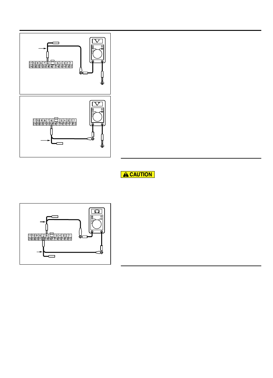
ZC5010390007

Harness side: C-301

Test 
harness

Test 
harness

(2)

Check  that  there  is  continuity  between  ETACS-ECU
connector terminals 6 and 7.

OK: No continuity

Q:Is the check result normal?

YES:

 Go to Step 37.

NO:

 Go to Step 26.

STEP 26. Check the wiring harness between joint connector
(CAN1) C-103 and combination meter connector C-03 for
line-to-line short. Measure the resistance at joint connector
(CAN1) C-103.

(1)

Disconnect joint connector (CAN1), and check that there is
continuity at the harness side of joint connector (CAN1).

CONTROLLER AREA NETWORK (CAN)

54D-171

DIAGNOSIS

ZC5010390008

Test harness

Harness side: C-103

Test harness

(2)

Check  that  there  is  continuity  between  joint  connector
(CAN1) terminals 3 and 14.

OK: No continuity

Q:Is the check result normal?

YES(vehicles with KOS):

 Go to Step 27.

YES(vehicles with WCM):

 Go to Step 28.

NO(vehicles with KOS or WCM):

 Go to Step 48.

STEP 27. Check the wiring harness between joint connector
(CAN1) C-103 and KOS-ECU connector C-102 for line-to-line
short. Measure the resistance at joint connector (CAN1)
C-103.

(1)

Disconnect joint connector (CAN1), and check that there is
continuity at the harness side of joint connector (CAN1).

ZC5010390009

Test 
harness

Harness side: C-103

Test 
harness

(2)

Check  that  there  is  continuity  between  joint  connector
(CAN1) terminals 8 and 21.

OK: No continuity

Q:Is the check result normal?

YES:

 Go to Step 29.

NO:

 Go to Step 49.

STEP 28. Check the wiring harness between joint connector
(CAN1) C-103 and WCM connector C-29 for line-to-line
short. Measure the resistance at joint connector (CAN1)
C-103.

(1)

Disconnect joint connector (CAN1), and check that there is
continuity at the harness side of joint connector (CAN1).

ZC5010390010

Test harness

Harness side: C-103

Test harness

(2)

Check  that  there  is  continuity  between  joint  connector
(CAN1) terminals 5 and 16.

OK: No continuity

Q:Is the check result normal?

YES:

 Go to Step 29.

NO:

 Go to Step 50.

STEP 29. Check the wiring harness between joint connector
(CAN1) C-103 and SRS-ECU connector C-28 for line-to-line
short. Measure the resistance at joint connector (CAN1)
C-103.

(1)

Disconnect joint connector (CAN1), and check that there is
continuity at the harness side of joint connector (CAN1).

54D-172

CONTROLLER AREA NETWORK (CAN)

DIAGNOSIS

ZC5010390011

Test harness

Harness side: C-103

Test harness

(2)

Check  that  there  is  continuity  between  joint  connector
(CAN1) terminals 1 and 12.

OK: No continuity

Q:Is the check result normal?

YES:

 Go to Step 30.

NO:

 Go to Step 51.

STEP 30. Check the wiring harness between joint connector
(CAN1) C-103 and occupant classification-ECU connector
D-31-2 for line-to-line short. Measure the resistance at joint
connector (CAN1) C-103.

(1)

Disconnect joint connector (CAN1), and check that there is
continuity at the harness side of joint connector (CAN1).

ZC5010390012

Test harness

Harness side: C-103

Test harness

(2)

Check  that  there  is  continuity  between  joint  connector
(CAN1) terminals 11 and 24.

OK: No continuity

Q:Is the check result normal?

YES(vehicles without hands free system):

 Go to Step 32.

YES(vehicles with hands free system):

 Go to Step 31.

NO:

 Go to Step 52.

STEP 31. Check the wiring harness between joint connector
(CAN1) C-103 and hands free module connector C-121 for
line-to-line short. Measure the resistance at joint connector
(CAN1) C-103.

(1)

Disconnect joint connector (CAN1), and check that there is
continuity at the harness side of joint connector (CAN1).

ZC5010390013

Test 
harness

Harness side: C-103

Test 
harness

(2)

Check  that  there  is  continuity  between  joint  connector
(CAN1) terminals 7 and 20.

OK: No continuity

Q:Is the check result normal?

YES:

 Go to Step 32.

NO:

 Go to Step 53.

STEP 32. Check the wiring harness between joint connector
(CAN1) C-103 and A/C-ECU connector C-109 for line-to-line
short. Measure the resistance at joint connector (CAN1)
C-103.

(1)

Disconnect joint connector (CAN1), and check that there is
continuity at the harness side of joint connector (CAN1).

CONTROLLER AREA NETWORK (CAN)

54D-173

DIAGNOSIS

ZC5010390014

Test harness

Harness side: C-103

Test harness

(2)

Check  that  there  is  continuity  between  joint  connector
(CAN1) terminals 9 and 22.

OK: No continuity

Q:Is the check result normal?

YES(vehicles without MMCS):

 Go to Step 33.

YES(vehicles with MMCS):

 Go to Step 34.

NO:

 Go to Step 54.

STEP 33. Check the wiring harness between joint connector
(CAN1) C-103 and radio and CD player or CD changer
connector C-16 for line-to-line short. Measure the
resistance at joint connector (CAN1) C-103.

(1)

Disconnect joint connector (CAN1), and check that there is
continuity at the harness side of joint connector (CAN1).

ZC5010390015

Test harness

Harness side: C-103

Test harness

(2)

Check  that  there  is  continuity  between  joint  connector
(CAN1) terminals 10 and 23.

OK: No continuity

Q:Is the check result normal?

YES(vehicles without satellite radio):

 Go to Step 36.

YES(vehicles with satellite radio):

 Go to Step 35.

NO:

 Go to Step 55.

STEP 34. Check the wiring harness between joint connector
(CAN1) C-103 and CAN box unit connector C-13 for line-to-
line short. Measure the resistance at joint connector (CAN1)
C-103.

(1)

Disconnect joint connector (CAN1), and check that there is
continuity at the harness side of joint connector (CAN1).

ZC5010390015

Test harness

Harness side: C-103

Test harness

(2)

Check  that  there  is  continuity  between  joint  connector
(CAN1) terminals 10 and 23.

OK: No continuity

Q:Is the check result normal?

YES(vehicles without satellite radio):

 Go to Step 36.

YES(vehicles with satellite radio):

 Go to Step 35.

NO:

 Go to Step 56.

STEP 35. Check the wiring harness between joint connector
(CAN1) C-103 and satellite radio tuner connector C-111 for
line-to-line short. Measure the resistance at joint connector
(CAN1) C-103.

(1)

Disconnect joint connector (CAN1), and check that there is
continuity at the harness side of joint connector (CAN1).

54D-174

CONTROLLER AREA NETWORK (CAN)

DIAGNOSIS


Content   ..  1170  1171  1172  1173   ..