Content .. 1161 1162 1163 1164 ..
Mitsubishi Outlander XL. Manual - part 1163
ZC5010400034
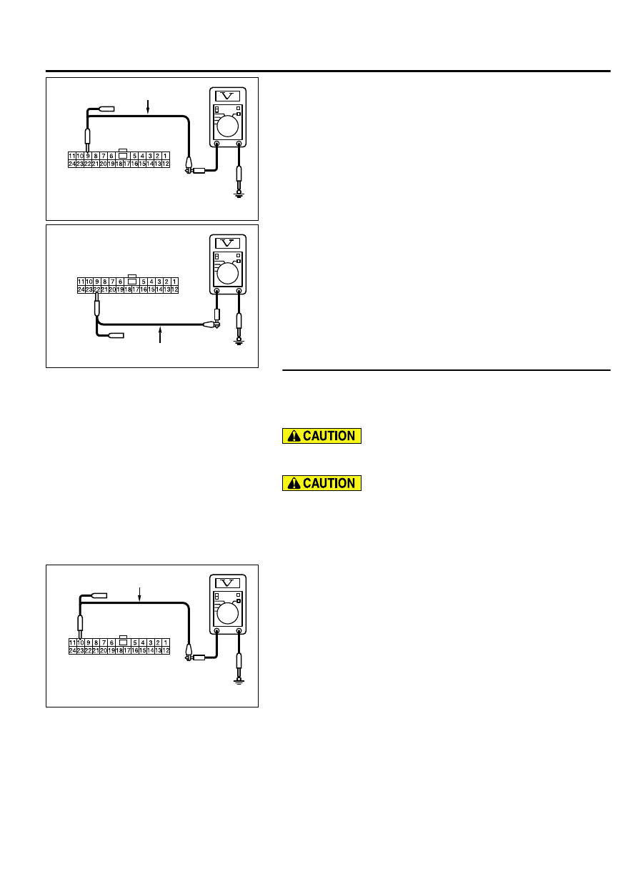
Harness side: C-103
Test harness
(3)
Measure the voltage between joint connector (CAN1)
terminal 9 and body ground.
OK: 4.7 volts or less
ZC5010400035
Harness side: C-103
Test harness
(4)
Measure the voltage between joint connector (CAN1)
terminal 22 and body ground.
OK: 4.7 volts or less
Q:Do all the voltages measure 4.7 volts or less?
YES(vehicles without MMCS):
Go to Step 20.
YES(vehicles with MMCS):
Go to Step 21.
NO:
Go to Step 30.
STEP 20. Check the wiring harness between joint connector
(CAN1) C-103 and radio and CD player or CD changer
connector C-16 for a short to power supply. Measure the
voltage at joint connector (CAN1) C-103.
A digital multimeter should be used. For details refer to P.
54D-8.
The test wiring harness should be used. For details refer
to P.54D-8.
(1)
Disconnect joint connector (CAN1), and measure the voltage
at the wiring harness side of joint connector (CAN1).
(2)
Turn the ignition switch to the ON position.
ZC5010400036
Harness side: C-103
Test harness
(3)
Measure the voltage between joint connector (CAN1)
terminal 10 and body ground.
OK: 4.7 volts or less
CONTROLLER AREA NETWORK (CAN)
54D-135
DIAGNOSIS