Content .. 1159 1160 1161 1162 ..
Mitsubishi Outlander XL. Manual - part 1161
ZC5010410026
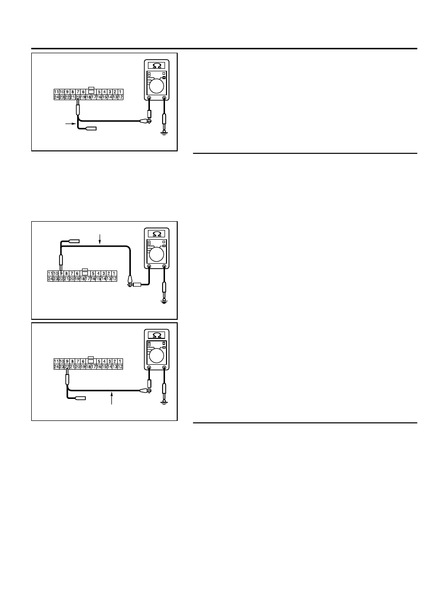
Harness side: C-103
Test
harness
(3)
Measure the resistance between joint connector (CAN1)
terminal 20 and body ground.
OK: 1 kiloohm or more
Q:Do all the resistances measure 1 kiloohm or more?
YES:
Go to Step 8.
NO:
Go to Step 29.
STEP 8. Check the wiring harness between joint connector
(CAN1) C-103 and A/C-ECU connector C-109 for a short to
ground. Measure the resistance at joint connector (CAN1)
C-103.
(1)
Disconnect joint connector (CAN1), and measure the
resistance at the wiring harness side of joint connector
(CAN1).
ZC5010410027
Harness side: C-103
Test harness
(2)
Measure the resistance between joint connector (CAN1)
terminal 9 and body ground.
OK: 1 kiloohm or more
ZC5010410028
Harness side: C-103
Test harness
(3)
Measure the resistance between joint connector (CAN1)
terminal 22 and body ground.
OK: 1 kiloohm or more
Q:Do all the resistances measure 1 kiloohm or more?
YES(vehicles without MMCS):
Go to Step 9.
YES(vehicles with MMCS):
Go to Step 10.
NO:
Go to Step 30.
STEP 9. Check the wiring harness between joint connector
(CAN1) C-103 and radio and CD player or CD changer
connector C-16 for a short to ground. Measure the
resistance at joint connector (CAN1) C-103.
(1)
Disconnect joint connector (CAN1), and measure the
resistance at the wiring harness side of joint connector
(CAN1).
CONTROLLER AREA NETWORK (CAN)
54D-127
DIAGNOSIS