Content .. 1155 1156 1157 1158 ..
Mitsubishi Outlander XL. Manual - part 1157
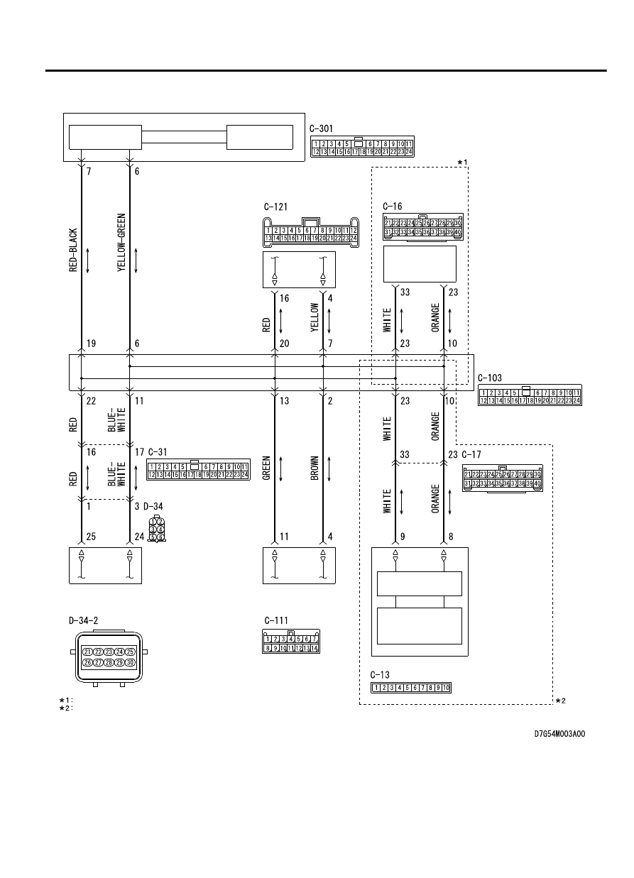
CAN Communication Circuit
ETACS-ECU
INTERFACE
CIRCUIT
INTERFACE
CIRCUIT
CAN DRIVE
CIRCUIT
HANDS FREE
MODULE
OCCUPANT
CLASSIFICATION-
ECU
SATELLITE
RADIO
TUNER
RADIO AND CD
PLAYER OR CD
CHANGER
NOTE
VEHICLES WITHOUT MITSUBISHI MULTI-COMMUNICATION SYSTEM (MMCS)
VEHICLES WITH MITSUBISHI MULTI-COMMUNICATION SYSTEM (MMCS)
CAN
TRANSCEIVER
CIRCUIT
CAN BOX UNIT
JOINT CONNECTOR
(CAN1)
CONTROLLER AREA NETWORK (CAN)
54D-111
DIAGNOSIS