Content .. 1152 1153 1154 1155 ..
Mitsubishi Outlander XL. Manual - part 1154
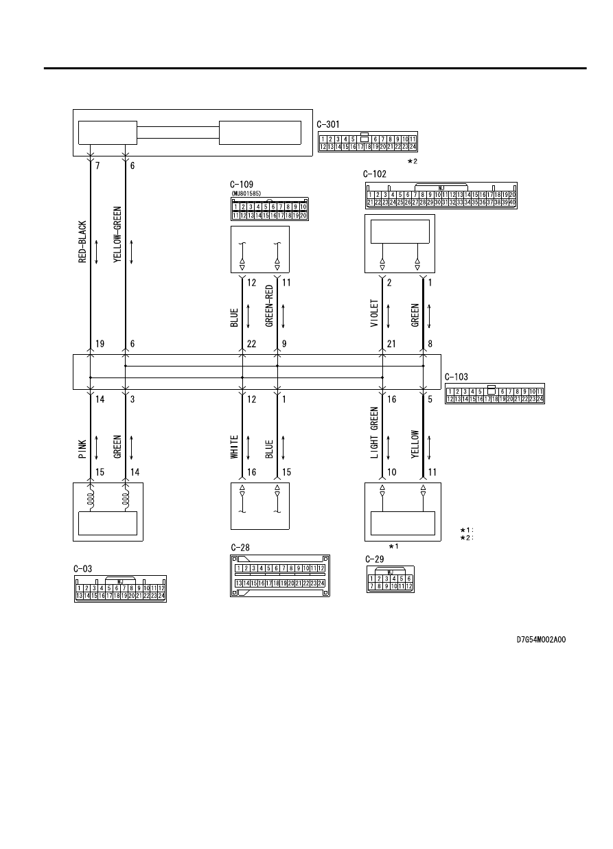
CAN Communication Circuit
ETACS-ECU
INTERFACE
CIRCUIT
CAN DRIVE
CIRCUIT
A/C-ECU
COMBINATION
METER
SRS-ECU
WCM
KOS-ECU
NOTE
VEHICLES WITH WCM
VEHICLES WITH KOS
CAN DRIVE
CIRCUIT
CAN DRIVE
CIRCUIT
CAN DRIVE
CIRCUIT
JOINT CONNECTOR
(CAN1)
CONTROLLER AREA NETWORK (CAN)
54D-99
DIAGNOSIS