Content .. 1149 1150 1151 1152 ..
Mitsubishi Outlander XL. Manual - part 1151
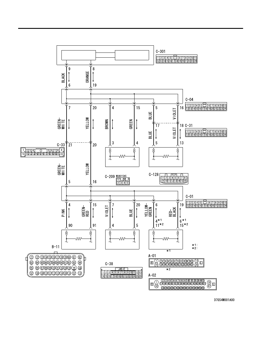
CAN Communication Circuit
ETACS-ECU
INTERFACE
CIRCUIT
CAN DRIVE
CIRCUIT
STEERING WHEEL
SENSOR
AWD-ECU
JOINT CONNECTOR
(CAN2)
JOINT CONNECTOR
(CAN3)
TRANSMISSION
CONTROL
MODULE
ASC-ECU
ABS-ECU
ENGINE
CONTROL
MODULE
NOTE
VEHICLES WITHOUT ASC
VEHICLES WITH ASC
CONTROLLER AREA NETWORK (CAN)
54D-87
DIAGNOSIS