Content .. 1129 1130 1131 1132 ..
Mitsubishi Outlander XL. Manual - part 1131
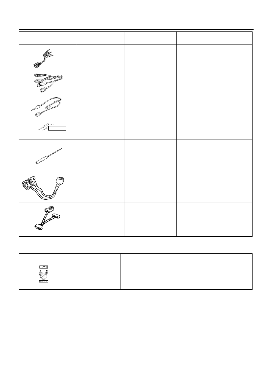
Tool
Tool number and
name
Supersession
Application
YB9912230000
Do not use
a
b
c
d
MB991223
a.
MB991219
b.
MB991220
c.
MB991221
d.
MB991222
Harness set
a.
Test harness
b.
LED harness
c.
LED
harness
adaptor
d.
Probe
General service tools Continuity check and voltage
measurement at harness wire or
connector for loose, corroded or
damaged terminals, or terminals
pushed back in the connector.
a.
Connector
pin
contact
pressure inspection
b.
Power circuit inspection
c.
Power circuit inspection
d.
Commercial tester connection
MB992006
MB992006
Extra fine probe
-
Continuity check and voltage
measurement at harness wire or
connector for loose, corroded or
damaged terminals, or terminals
pushed back in the connector.
MB991970
MB991970
ABS check harness
-
Measure
the
voltage
and
resistance at the ABS-ECU
MB991952
MB991952
ABS check harness
-
Measure
the
voltage
and
resistance at the ASC-ECU
TEST EQUIPMENT
M15408300043USA0000010000
Test equipment
Name
Use
ZC3000010000
Digital multimeter
Checking CAN bus circuit (for resistance and voltage
measurements)
CONTROLLER AREA NETWORK (CAN)
54D-7
TEST EQUIPMENT