Mitsubishi Outlander XL. Manual - part 1101


  Index      Mitsubishi     Mitsubishi Outlander XL - service repair manual 2007 year


Search            


Content   ..  1099  1100  1101  1102   ..


Mitsubishi Outlander XL. Manual - part 1101


YES:

 The trouble can be an intermittent malfunction

(Refer to GROUP 00, How to use Troubleshooting/inspection
Service Points, How to Cope with Intermittent
Malfunction P.00-15).

NO:

 The wiring harness may be damaged or the connector

(s) may have loose, corroded or damaged terminals, or
terminals pushed back in the connector. Repair the wiring
harness as necessary.

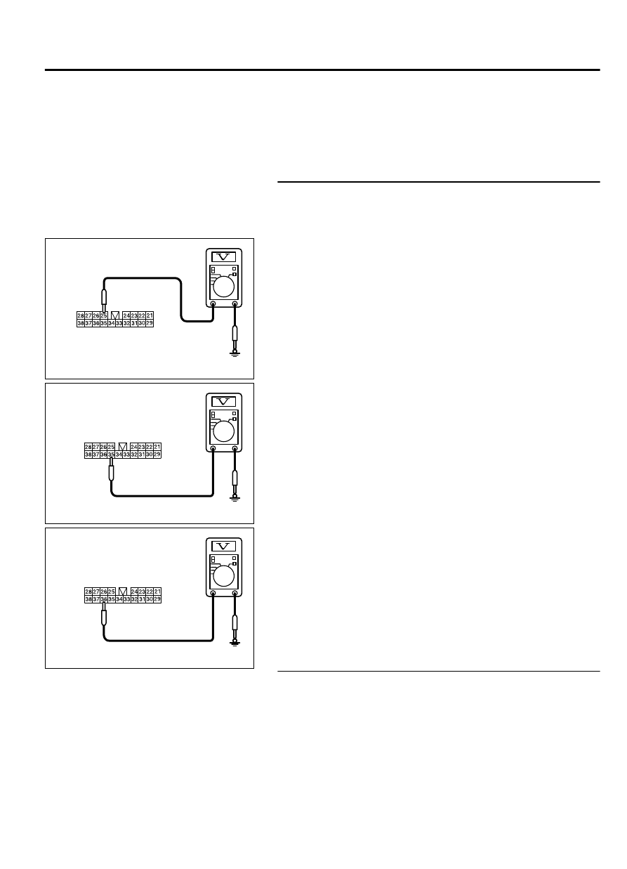
STEP 5. Check the power supply circuit to the ETACS-ECU.
Measure the voltage at audio amplifier connector D-126.

(1)

Disconnect audio amplifier connector D-126, and measure
the voltage available at the wiring harness-side connector.

ZC5010400045

Harness side: D-126

(2)

Measure the voltage between terminal 25 and ground.

OK: The voltage should measure approximately 12
volts (battery positive voltage).

ZC5010400046

Harness side: D-126

(3)

Measure the voltage between terminal 35 and ground.

OK: The voltage should measure approximately 12
volts (battery positive voltage).

ZC5010400047

Harness side: D-126

(4)

Measure the voltage between terminal 36 and ground.

OK: The voltage should measure approximately 12
volts (battery positive voltage).

Q:Is the measured voltage approximately 12 volts (battery

positive voltage)?

YES:

 Go to Step 7.

NO:

 Go to Step 6.

STEP 6. Check the wiring harness between audio amplifier
connector D-126 (terminal 25, 35, 36) and fusible link (36).

NOTE: 

Also check intermediate connector C-129 for loose,

corroded, or damaged terminals, or terminals pushed back in
the connector. If intermediate connector C-129 is damaged,
repair or replace the connector as described in GROUP 00E,
Harness Connector Inspection P.00E-2.

Check the power supply line for open circuit and short circuit.

AUDIO AND NAVIGATION SYSTEM

54B-85

DIAGNOSIS

Q:Is the wiring harness between audio amplifier connector

D-126 (terminal 25, 35, 36) and fusible link (36) in good

condition?

YES:

 Go to Step 7.

NO:

 The wiring harness may be damaged or the connector

(s) may have loose, corroded or damaged terminals, or
terminals pushed back in the connector. Repair the wiring
harness as necessary.

STEP 7. Check audio visual navigation unit connector C-06
and audio amplifier connector D-127 for loose, corroded or
damaged terminals, or terminals pushed back in the
connector.

Q:Is audio visual navigation unit connector C-06 and audio

amplifier connector D-127 in good condition?

YES:

 Go to Step 8.

NO:

 Repair or replace the damaged component(s). Refer to

GROUP 00E, Harness Connector Inspection P.00E-2.

STEP 8. Check the wiring harness between audio visual
navigation unit connector C-06 (terminal 82) and audio
amplifier connector D-127 (terminal 3)

NOTE: 

Also check intermediate connectors C-15 and C-22 for

loose, corroded, or damaged terminals, or terminals pushed
back in the connector. If intermediate connector C-15 or
C-22 is damaged, repair or replace the connector as
described in GROUP 00E, Harness Connector Inspection P.
00E-2.

Check the communication lines for open circuit.

Q:Is  the  wiring  harness  between  audio  visual  navigation

unit  connector  C-06  (terminal  82)  and  audio  amplifier

connector D-127 (terminal 3) in good condition?

YES:


Go to Step 9.

NO:

 The wiring harness may be damaged or the connector

(s) may have loose, corroded or damaged terminals, or
terminals pushed back in the connector. Repair the wiring
harness as necessary.

STEP 9. Retest the system
Replace the audio amplifier, then check that the audio sound is
output.

Q:Is the check result normal?

YES:

 The trouble can be an intermittent malfunction

(Refer to GROUP 00, How to use Troubleshooting/inspection
Service Points, How to Cope with Intermittent
Malfunction P.00-15).

NO:

 Replace the audio visual navigation unit.

54B-86

AUDIO AND NAVIGATION SYSTEM

DIAGNOSIS

Inspection Procedure 3: No sound is heard from one of the speakers. <Vehicles without
audio amplifier>

M15410800358USA0000010001

Before replacing the ECU, ensure that the power
supply  circuit,  the  ground  circuit  and  the
communication circuit are normal.

AUDIO AND NAVIGATION SYSTEM

54B-87

DIAGNOSIS

Speaker System Circuit

TWEETER
(RH)

AUDIO VISUAL NAVIGATION UNIT

REAR DOOR SPEAKER (LH)

REAR DOOR SPEAKER (RH)

FRONT DOOR
SPEAKER (RH)

FRONT DOOR
SPEAKER (LH)

TWEETER
(LH)

54B-88

AUDIO AND NAVIGATION SYSTEM

DIAGNOSIS


Content   ..  1099  1100  1101  1102   ..