Mitsubishi Outlander XL. Manual - part 1085


  Index      Mitsubishi     Mitsubishi Outlander XL - service repair manual 2007 year


Search            


Content   ..  1083  1084  1085  1086   ..


Mitsubishi Outlander XL. Manual - part 1085


STEP 4. Check the wiring harness between ETACS-ECU
connector C-317 (terminal 1) and radio and CD player or CD
changer connector C-16 (terminal 30).

Check the power supply lines (battery power supply) for open
circuit.

Q:Is  the  wiring  harness  between  ETACS-ECU  connector

C-317 (terminal 1) and radio and CD player or CD changer

connector C-16 (terminal 30) in good condition?

YES:

 Go to Step 5.

NO:

 The wiring harness may be damaged or the connector

(s) may have loose, corroded or damaged terminals, or
terminals pushed back in the connector. Repair the wiring
harness as necessary.

STEP 5. Using scan tool MB991958, check data list.
Check the input signal of ACC relay.

Turn the ignition switch to the ACC position.

Item No.

Item name

Normal
conditions

Item 288

ACC switch

ON

OK: Normal condition is displayed.

Q:Is the check result normal?

YES:

 Go to Step 6.

NO:

 Refer to GROUP 54Ad, Troubleshooting - Inspection

Procedure 1 "The ignition switch (ACC) signal is not
received" P.54Ad-61.

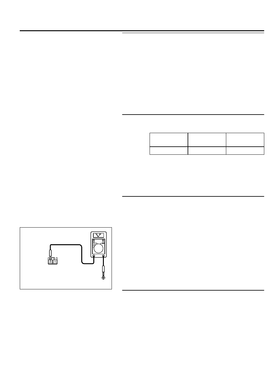
STEP 6. Check the power supply circuit to the ETACS-ECU.
Measure the voltage at ETACS-ECU connector C-309.

(1)

Disconnect  the  connector,  and  measure  at  the  wiring
harness-side connector.

(2)

Turn the ignition switch to the "ACC" position.

ZC5010400042

Harness side: C-309

(3)

Measure the voltage between terminal 2 and ground.

OK: Battery voltage

Q:Is the measured voltage battery voltage?

YES:

 Go to Step 8.

NO:

 Go to Step 7.

STEP 7. Check the wiring harness between ETACS-ECU
connector C-309 (terminal 2) and fusible link (37)

Check the power supply line for open circuit and short circuit.

Q:Is  the  wiring  harness  between  ETACS-ECU  connector

C-309 (terminal 2) and fusible link (37) in good condition?

YES:

 Go to Step 8.

NO:

 The wiring harness may be damaged or the connector

(s) may have loose, corroded or damaged terminals, or

AUDIO AND NAVIGATION SYSTEM

54B-21

DIAGNOSIS

terminals pushed back in the connector. Repair the wiring
harness as necessary.

STEP 8. Check ETACS-ECU connector C-315 for loose,
corroded or damaged terminals, or terminals pushed back
in the connector.

Q:Is ETACS-ECU connector C-315 in good condition?

YES:

 Go to Step 9.

NO:

 Repair or replace the damaged component(s). Refer to

GROUP 00E, Harness Connector Inspection P.00E-2. The
steering remote control switch should work normally.

STEP 9. Check the power supply circuit to the ETACS-ECU.
Measure the voltage at ETACS-ECU connector C-315.

(1)

Disconnect the connector, and measure at the ETACS-ECU
side connector.

(2)

Turn the ignition switch to the "ACC" position.

ZC5010400048

Component side: C-315

(3)

Measure voltage between terminal 9 and ground.

OK: Battery voltage

Q:Is the measured voltage battery voltage?

YES:

 Go to Step 10.

NO:

 Replace the ETACS-ECU.

STEP 10. Check the wiring harness between radio and CD
player or CD changer connector C-16 (terminal 21) and
ETACS-ECU connector C-315 (terminal 9).

Check the power supply line for open circuit.

Q:Is the wiring harness between radio and CD player or CD

changer  connector  C-16  (terminal  21)  and  ETACS-ECU

connector C-315 (terminal 9) in good condition?

YES:


Go to Step 11.

NO:

 The wiring harness may be damaged or the connector

(s) may have loose, corroded or damaged terminals, or
terminals pushed back in the connector. Repair the wiring
harness as necessary.

STEP 11. Check the ground circuit to the radio and CD
player or CD changer. Measure the resistance at radio and
CD player or CD changer connector C-16.

(1)

Disconnect the connector, and measure at the wiring harness
side.

54B-22

AUDIO AND NAVIGATION SYSTEM

DIAGNOSIS

ZC5010410044

Harness side: C-16

(2)

Measure resistance between terminal 40 and ground.

OK: The resistance should be 2 ohm or less.

Q:Is the measured resistance 2 ohms or less?

YES:

 Go to Step 13.

NO:

 Go to Step 12.

STEP 12. Check the wiring harness between radio and CD
player or CD changer connector C-16 (terminal 40) and
ground.

Check the ground wires for open circuit.

Q:Is the wiring harness between radio and CD player or CD

changer connector C-16 (terminal 40) and ground in good

condition?

YES:

 Check the trouble symptom.

NO:

 The wiring harness may be damaged or the connector

(s) may have loose, corroded or damaged terminals, or
terminals pushed back in the connector. Repair the wiring
harness as necessary.

STEP 13. Retest the system
Check if the radio and CD player or CD changer power is turned
ON.

Q:Is the check result normal?

YES:

 The trouble can be an intermittent malfunction

(Refer to GROUP 00, How to use Troubleshooting/inspection
Service Points - How to Cope with Intermittent
Malfunction P.00-15).

NO:

 Replace the radio and CD player or CD changer.

Inspection Procedure 2: No sound is heard. <Vehicles with audio amplifier>

M15410800356USA0000010000

Before replacing the ECU, ensure that the power
supply  circuit,  the  ground  circuit  and  the
communication circuit are normal.

AUDIO AND NAVIGATION SYSTEM

54B-23

DIAGNOSIS

Audio System Circuit

RELAY
BOX

AUDIO AMPLIFIER

FUSIBLE
LINK

36

RADIO AND CD CHANGER

54B-24

AUDIO AND NAVIGATION SYSTEM

DIAGNOSIS


Content   ..  1083  1084  1085  1086   ..