Content .. 1079 1080 1081 1082 ..
Mitsubishi Outlander XL. Manual - part 1081
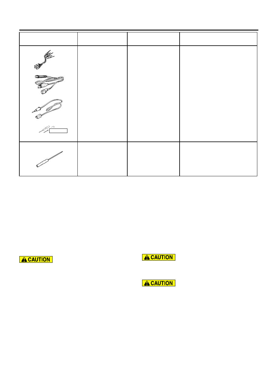
Tool
Tool number and
name
Supersession
Application
YB9912230000
Do not use
a
b
c
d
MB991223
a.
MB991219
b.
MB991220
c.
MB991221
d.
MB991222
Harness set
a.
Test harness
b.
LED harness
c.
LED
harness
adaptor
d.
Probe
General service tools Continuity check and voltage
measurement at harness wire or
connector for loose, corroded or
damaged terminals, or terminals
pushed back in the connector.
a.
Connector
pin
contact
pressure inspection
b.
Power circuit inspection
c.
Power circuit inspection
d.
Commercial tester connection
MB992006
MB992006
Extra fine probe
-
Continuity check and voltage
measurement at harness wire or
connector for loose, corroded or
damaged terminals, or terminals
pushed back in the connector.
DIAGNOSIS
STANDARD FLOW OF DIAGNOSTIC TROUBLESHOOTING
M15410800006USA0000010000
Refer to GROUP 00 - Troubleshooting contents P.
00-6.
TROUBLESHOOTING FOR NOISE
M15410800323USA0000010000
AM/FM RADIO AND CD PLAYER
The noise is generated during the engine run.
Check that no noise of external origin is present.
Because the signal reception becomes poor
indoors, check in the open air. If this check is
neglected, the source of noise cannot be
determined, resulting in a false recognition.
Therefore, be sure to perform this check.
When implementing the noise prevention, start
the prevention from the object causing the
strongest noise.
Check that the audio main body and others are
securely grounded.
AUDIO AND NAVIGATION SYSTEM
54B-5
DIAGNOSIS