Content .. 1055 1056 1057 1058 ..
Mitsubishi Outlander XL. Manual - part 1057
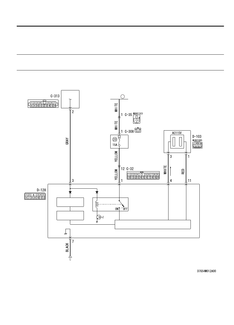
SYMPTOM PROCEDURES
INSPECTION PROCEDURE 1: Even when the equipment (power consumption is 100 W
or less) is connected, the equipment cannot be used.
M15410400007USA0000010000
AC Power Supply Circuit
34
FUSIBLE
LINK
ETACS-ECU
RELAY
BOX
AC OUTLET
AC INVERTER
POWER
SUPPLY
CPU
INVERTER
ACCESSORY
54Ae-7
AC POWER SUPPLY