Content .. 1040 1041 1042 1043 ..
Mitsubishi Outlander XL. Manual - part 1042
⦆
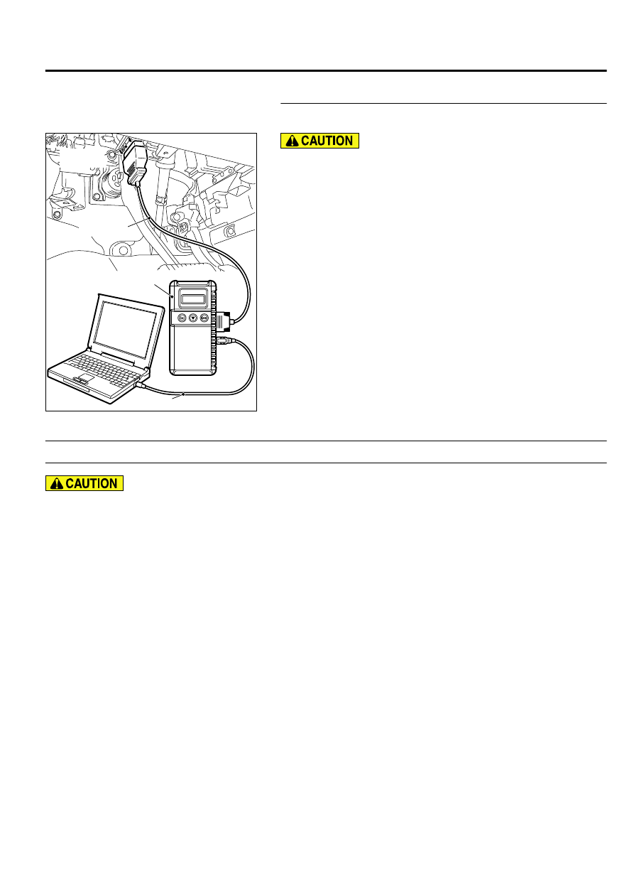
MB991910: M.U.T.-III Main Harness A (Vehicles with
CAN communication system)
Recheck for diagnostic trouble code.
Check again if the DTC is set to the ETACS-ECU.
ZC501967
AC404789
ZC5019680000
MB991824
MB991827
MB991910
Data link
connector
To prevent damage to scan tool MB991958, always turn the
ignition switch to the "LOCK" (OFF) position before
connecting or disconnecting scan tool MB991958.
(1)
Connect scan tool MB991958. Refer to "How to connect the
Scan Tool (M.U.T.-III) P.54Ad-5."
(2)
Turn the ignition switch to the "ON" position.
(3)
Perform the variant coding to the ETACS-ECU.
(4)
Erase the DTC.
(5)
Turn the ignition switch from "LOCK" (OFF) position to "ON"
position.
(6)
Check if DTC is set.
(7)
Turn the ignition switch to the "LOCK" (OFF) position.
Q:Is the DTC set?
YES:
Replace with the coded ETACS-ECU.
NO:
The diagnosis is complete.
DTC B2206: Chassis number does not match
M15410600066USA0000010000
If DTC B2206 is set, always diagnose the CAN bus
line.
TROUBLE JUDGMENT
If the registered chassis number is different from the
chassis number transmitted on the CAN bus lines, the
ETACS-ECU sets DTC B2206.
JUDGMENT CRITERIA
If the chassis number registered to ETACS-ECU and
the chassis number on CAN bus lines do not match,
the ETACS-ECU determines that a problem has
occurred.
TROUBLESHOOTING HINTS
⦆
Chassis number not written
⦆
The ETACS-ECU may be defective.
⦆
The engine control module may be defective.
⦆
The CAN bus line may be defective.
DIAGNOSIS
Required Special Tools:
⦆
MB991958: Scan Tool (M.U.T.-III Sub Assembly)
⦆
MB991824: Vehicle Communication Interface (V.C.I.)
⦆
MB991827: M.U.T.-III USB Cable
⦆
MB991910: M.U.T.-III Main Harness A (Vehicles with
CAN communication system)
ETACS
54Ad-47
DIAGNOSIS