Content .. 1039 1040 1041 1042 ..
Mitsubishi Outlander XL. Manual - part 1041
DIAGNOSIS
Required Special Tools:
⦆
MB991958: Scan Tool (M.U.T.-III Sub Assembly)
⦆
MB991824: Vehicle Communication Interface (V.C.I.)
⦆
MB991827: M.U.T.-III USB Cable
⦆
MB991910: M.U.T.-III Main Harness A (Vehicles with
CAN communication system)
Recheck for diagnostic trouble code.
Check again if the DTC is set to the ETACS-ECU.
ZC501967
AC404789
ZC5019680000
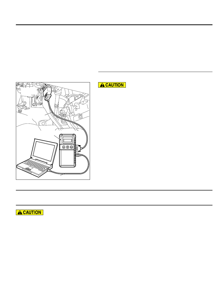
MB991824
MB991827
MB991910
Data link
connector
To prevent damage to scan tool MB991958, always turn the
ignition switch to the "LOCK" (OFF) position before
connecting or disconnecting scan tool MB991958.
(1)
Connect scan tool MB991958. Refer to "How to connect the
Scan Tool (M.U.T.-III) P.54Ad-5."
(2)
Turn the ignition switch to the "ON" position.
(3)
Erase the DTC.
(4)
Turn the ignition switch from "LOCK" (OFF) position to "ON"
position.
(5)
Check if DTC is set.
(6)
Turn the ignition switch to the "LOCK" (OFF) position.
Q:Is the DTC set?
YES:
Replace with the coded ETACS-ECU.
NO:
The diagnosis is complete.
DTC B210A: +B power supply (low input)
DTC B210B: +B power supply (high input)
M15410600064USA0000010000
Before replacing the ECU, ensure that the input
and output signal circuits are normal.
ETACS
54Ad-43
DIAGNOSIS