Content .. 1007 1008 1009 1010 ..
Mitsubishi Outlander XL. Manual - part 1009
DIAGNOSIS
Required Special Tools:
⦆
MB991958: Scan Tool (M.U.T.-III Sub Assembly)
⦆
MB991824: Vehicle Communication Interface (V.C.I.)
⦆
MB991827: M.U.T.-III USB Cable
⦆
MB991910: M.U.T.-III Main Harness A (Vehicles with
CAN communication system)
STEP 1. License plate light operation check
Check that the license plate light illuminates normally.
Q:Does license plate light work normally?
YES:
Go to Step 2.
NO:
Replace the ETACS-ECU.
STEP 2. Using scan tool MB991958, read the diagnostic
trouble code.
ZC501967
AC404789
ZC5019680000
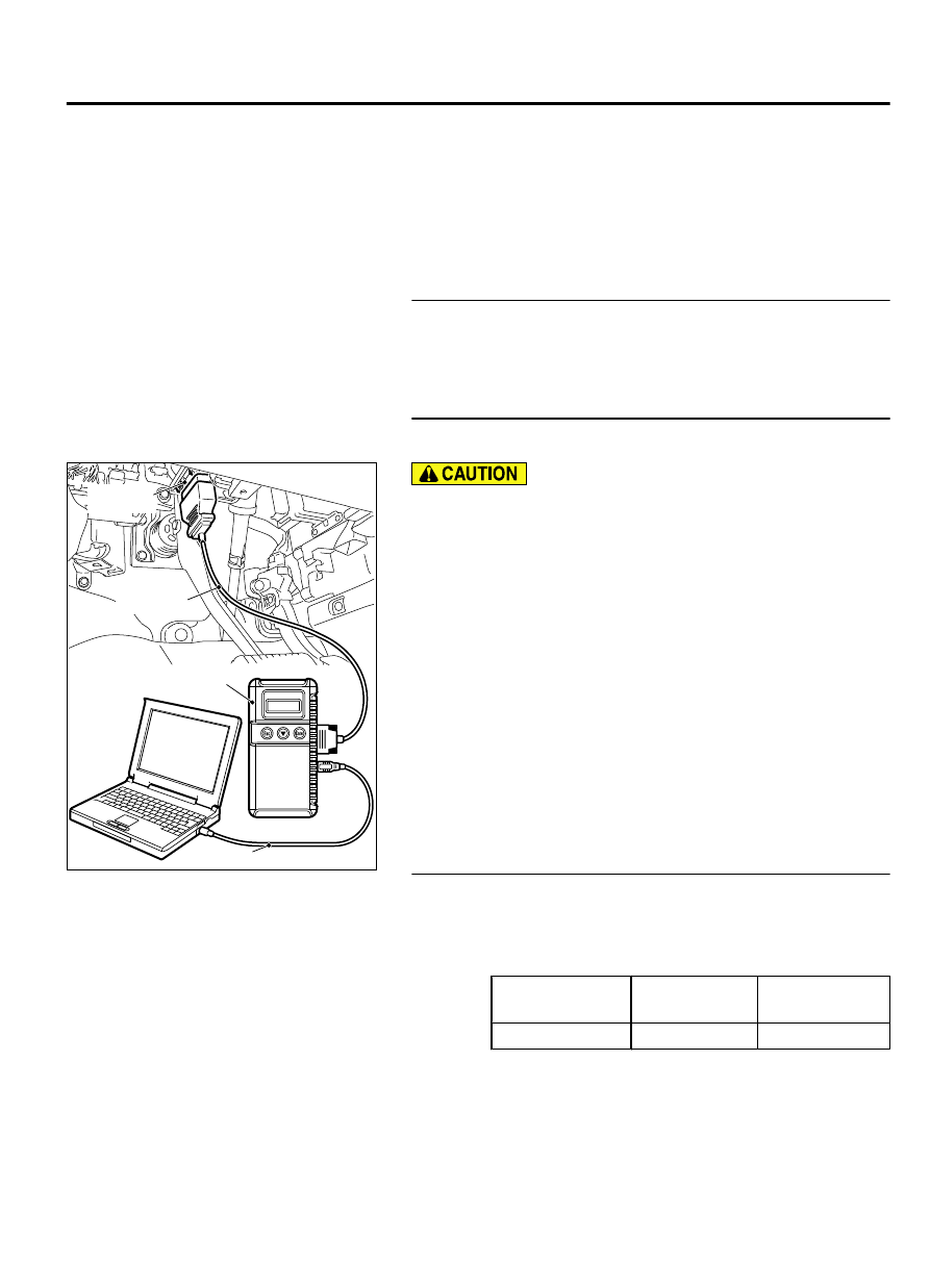
MB991824
MB991827
MB991910
Data link
connector
To prevent damage to scan tool MB991958, always turn the
ignition switch to the "LOCK" (OFF) position before
connecting or disconnecting scan tool MB991958.
(1)
Connect scan tool MB991958. Refer to "How to connect scan
too (M.U.T.-III) P.54Ac-99."
(2)
Turn the ignition switch to the "ON" position.
(3)
Check whether the ETACS-ECU related DTC is set.
(4)
Turn the ignition switch to the "LOCK" (OFF) position.
Q:Is the DTC set?
YES:
Diagnose the ETACS-ECU. Refer to GROUP 54Ad,
NO:
Go to Step 3.
STEP 3. Using scan tool MB991958, check data list.
Use the ETACS-ECU data list to check the signals related to the
taillight illumination.
⦆
Turn the ignition switch to the "ACC" position.
⦆
Turn the taillight switch to the "ON" position.
Item No.
Item name
Normal
conditions
Item 218
Tail light
ON
Q:Does scan tool MB991958 display the items "Tail light" as
normal condition?
YES<Normal condition is displayed for item.>:
Go to Step
4.
LIGHTING
54Ac-109
DIAGNOSIS