Mitsubishi Outlander XL. Manual - part 75


  Index      Mitsubishi     Mitsubishi Outlander XL - service repair manual 2007 year


Search            


Content   ..  73  74  75  76   ..


Mitsubishi Outlander XL. Manual - part 75


CABLES AND WIRES CHECK

M10009300010USA0000010000

ZC600195AA00

ZC600196AA00

1.

Check connections for looseness, rust, and stains.

2.

Check terminals and wires for corrosion.

3.

Check terminals and wires for open circuit or impending open
circuit.

4.

Check  wire  insulation  and  coating  for  damage,  cracks,  and
wear.

5.

Check  conductive  parts  of  terminals  for  contact  with  other
metallic parts (vehicle body and other parts).

6.

Check  grounding  parts  to  verify  that  there  is  complete
continuity between attaching bolt(s) and vehicle body.

7.

Check for incorrect wiring.

8.

Check  that  harnesses  are  secured  to  prevent  contact  with
sharp edges and corners or hot parts (exhaust manifold, pipe,
etc.).

9.

Check that harnesses are secured firmly to provide enough
clearance from the fan pulley, fan belt, and other rotating or
moving parts.

10.

Check that the harnesses between fixed parts (such as the
vehicle body) and vibrating parts (such as the engine) are
long enough to allow for vibration and movement.
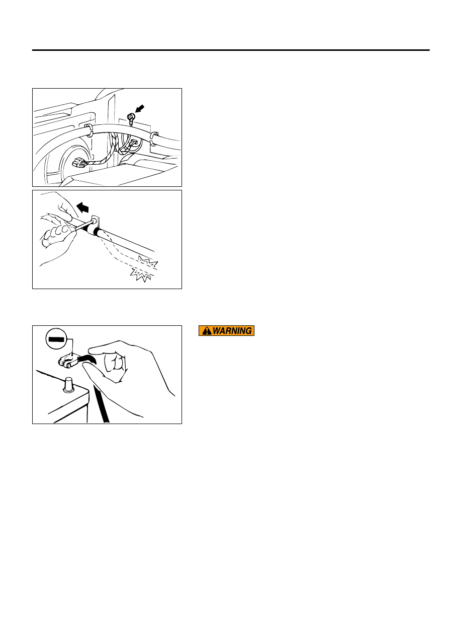
BATTERY HANDLING

M10009300011USA0000010000

ZC600197AA00

Battery  posts,  terminals  and  related  accessories  contain
lead  and  lead  compounds.  WASH  HANDS  AFTER
HANDLING.
When  checking  or  servicing  does  not  require  power  from  the
vehicle battery, be sure to disconnect the cable from the battery
(-) terminal. This will prevent problems that could be caused by
a  short  circuit.  Disconnect  the  (-)  battery  terminal  first  and
reconnect it last.

GENERAL ELECTRICAL SYSTEM CHECK

M10009300012USA0000010000

A circuit consists of the power supply, switch, relay,
load, ground, etc. There are various methods to check
a  circuit  including  an  overall  check,  voltage  check,

short-circuit check, and continuity check. Each of the
methods  briefly  described  below  applies  only  to
circuits similar to the illustration.

GENERAL <ELECTRICAL>

00E-13

HOW TO DIAGNOSE

VOLTAGE CHECK

ZC6001980000

Power supply

Fuse

Switch

Motor

(3)

ON  (2)

OFF

(1)

Test light
(or voltmeter)

1.

Ground one lead wire of the test light. If a voltmeter is used
instead of the test light, ground the grounding side lead wire.

2.

Connect the other lead wire of the test light to the power side
terminal of the switch connector. The test light should come
on or the voltmeter should indicate a voltage.

3.

Then,  connect  the  test  light  or  voltmeter  to  the  motor
connector. The test light should not come on, or the voltmeter
should indicate no voltage. When the switch is turned ON in
this  state,  the  test  light  should  come  on,  or  the  voltmeter
should indicate a voltage, with the motor starting to run.

4.

The circuit illustrated here is normal. If there is any problem,
such as the motor failing to run, check voltages beginning at
the  connector  nearest  to  the  motor  until  the  faulty  part  is
identified.

SHORT-CIRCUIT CHECK

Because the fuse has blown, it is probable that there is a short
circuit. Follow the procedures below to narrow down the short-
circuit location.

00E-14

GENERAL <ELECTRICAL>

HOW TO DIAGNOSE

STEP 1. Remove the blown fuse and connect the test light
across the fuse terminals (Circuit switch: OFF).

ZC6001990000

Power supply

Switch

OFF

Illumination light

Test light

Fuse block
(remove the fuse)

Short-circuit
location

Q:Does the test light illuminate?

YES:

 Short-circuit exists between the fuse block and the

switch. Repair the harness between the fuse block and the
switch.

NO:

 Go to Step 2.

STEP 2. Turn the switch ON and disconnect the illumination
light connector.

ZC6002000000

Power supply

Switch

ON

Illumination light

Test light

Fuse block
(remove 
the fuse)

Disconnect
the load

Short-circuit
location

Q:Does the test light illuminate?

YES:

 Short-circuit exists between the switch and the

connector. Repair the harness between the switch and the
connector.

NO:

 Short-circuit exists between the connector and the

illumination light. Repair the harness between the
connector and the illumination light.

GENERAL <ELECTRICAL>

00E-15

HOW TO DIAGNOSE

ZC6002010000

Power supply

Switch

ON

Illumination light

Test light

Fuse block
(remove the fuse)

Disconnect
the load

Short-circuit
location

CONTINUITY CHECK

ZC6002040000

Self-powered test light 
(or ohmmeter)

1 4

2 3

ON

OFF

ON

OFF

1.

When  the  switch  is  in  the  “OFF”  position  and  the  contact
points of terminals 1 and 2 are connected, the self-powered
test light should illuminate or the ohmmeter should read 0
ohm.

2.

When the switch is the “ON” position and the contact points
of terminals 3 and 4 are connected, the self-powered test light
should come on or the ohmmeter should read 0 ohm.

00E-16

GENERAL <ELECTRICAL>

HOW TO DIAGNOSE


Content   ..  73  74  75  76   ..