Mitsubishi Outlander XL. Manual - part 73


  Index      Mitsubishi     Mitsubishi Outlander XL - service repair manual 2007 year


Search            


Content   ..  71  72  73  74   ..


Mitsubishi Outlander XL. Manual - part 73


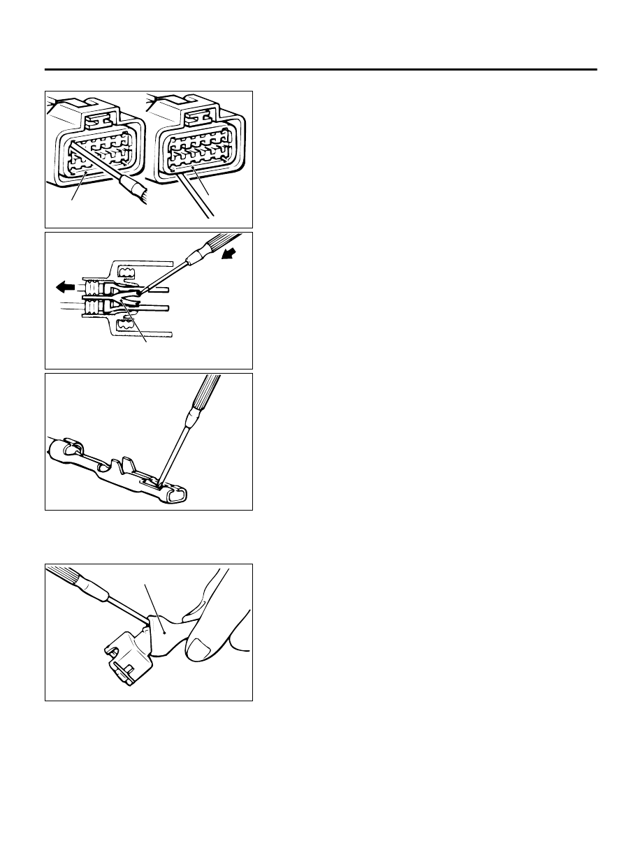
RECTANGULAR WATERPROOF CONNECTOR

ZC6001700000

Front 
holder

Front holder

1.

Disengage the front holder with a screwdriver and remove it.

ZC6001710000

Housing lance

2.

Insert the tip of a screwdriver [0.8 mm (0.03 inch) width] into
the connector as shown in the figure, push it lightly to raise the
housing lance, and pull out the terminal.

ZC600172AA00

3.

Press the contact point to the male terminal down by holding
a  screwdriver  [1.4  mm  (0.06  inch)  width]  as  shown  in  the
figure. Lightly squeeze the outer edge so the flats are parallel
with the bottom.


INJECTOR CONNECTOR

ZC600173

Waterproof cap

0000

1.

Remove the waterproof cap.

GENERAL <ELECTRICAL>

00E-5

HARNESS CONNECTOR INSPECTION

ZC6001740000

Terminal lance

2.

Insert the tip of a screwdriver [1.4 mm (0.06 inch) width] into
the  connector  as  shown  in  the  figure,  press  in  the  terminal
lance, and pull out the terminal.

ZC6000175AA00

Make  sure  the  lance  is  pressed  in  before  the  terminal  is
inserted into the connector.

3.

Press the contact point to the male terminal down by holding
a  screwdriver  [1.4  mm  (0.06  inch)  width]  as  shown  in  the
figure.

HOW TO DIAGNOSE

POINT FOR DIAGNOSIS

M10009300013USA0000010000

The  most  important  point  in  troubleshooting  is  to
determine  “Probable  Cause.”  Once  the  probable
causes are determined, parts to be checked can be
limited  to  those  associated  with  such  probable

causes.  The  determination  of  the  probable  causes
must be based on a theory and be supported by facts
and must not be based on intuition only.

TROUBLESHOOTING STEPS

M10009300003USA0000010000

If an attempt is made to solve a problem without going
through  correct  steps  for  troubleshooting,  the
symptoms could become more complicated, resulting

in  failure  to  determine  the  causes  correctly  and
making incorrect repairs. The four steps below should
be followed in troubleshooting.

00E-6

GENERAL <ELECTRICAL>

HOW TO DIAGNOSE

ZC600177

3

Checking of Parts Associated with
Probable Causes and Determination
of Faulty Parts

2 Determination of Probable Causes

4 Repair and Confirmation

Observe the symptom carefully. Check if there are also 
other problems.

In determining the probable causes, it is necessary to 
study the wiring diagram to understand the circuit as a 
system. Knowledge of switches, relays and other parts is 
necessary for accurate analysis. The causes of similar 
problems in the past must be taken into account.

Troubleshooting is carried out by making step-by-step 
checks until the cause is found.

After the problems are corrected, be sure to check that the
system operates correctly. Also check that new problems 
have not been caused by the repair.

0000

1 Observation of Problem Symptoms

INFORMATION FOR DIAGNOSIS

M10009300004USA0000010000

This manual contains the harness diagrams as well
as  the  individual  circuit  drawings,  operational
explanations,  and  troubleshooting  hints  for  each
component.  The  information  is  presented  in  the
following manner:

1.

Connector diagrams show the connector positions,
etc., on the actual vehicle as well as the harness
path.

2.

Circuit  diagrams  show  the  configuration  of  the
circuit with all switches in their normal positions.

3.

Operational explanations include circuit drawings of
current flow when the switch is operated and how
the component reacts.

4.

Troubleshooting hints include numerous examples
of problems which might occur, traced backward in
a  common-sense  manner  to  the  origin  of  the
trouble. Problems whose origins may not be found
in  this  manner  are  pursued  through  the  various
system circuits.

NOTE: 

Components of MFI, ETACS, etc. with ECU do

not include 3 and 4 above. For this information,
refer to a relevant group which includes details
of these components.

GENERAL <ELECTRICAL>

00E-7

HOW TO DIAGNOSE

INSPECTION

M10009300005USA0000010000

ZC600178

Click

0000

1.

Sight and sound checks
Check  relay  operation,  blower  motor  rotation,  light
illumination, etc. Listen for a “click” when some relay covers
are pushed down.

ZC600179AA00

2.

Simple checks
For example, if a headlight does not come on and a faulty fuse
or poor grounding is suspected, replace the fuse with a new
one.  Or  use  a  jumper  wire  to  ground  the  light  to  the  body.
Determine which part(s) is/are responsible for the problem.

ZC6001800000

Selector knob

Pointer

3.

Checking with instruments
Use an appropriate instrument in an adequate range and read
the indication correctly.

INSPECTION INSTRUMENTS

M10009300006USA0000010000

For inspection, use the following instruments:

ZC600181AA00

Never use a test light for checking ECU-related circuits or
ECUs.

1.

Test light
A test light consists of a 12V bulb and lead wires. It is used to
check voltages or short circuits.

00E-8

GENERAL <ELECTRICAL>

HOW TO DIAGNOSE


Content   ..  71  72  73  74   ..