Mitsubishi Outlander XL. Manual - part 49


  Index      Mitsubishi     Mitsubishi Outlander XL - service repair manual 2007 year


Search            


Content   ..  47  48  49  50   ..


Mitsubishi Outlander XL. Manual - part 49


Classifications of major maintenance / service points

When there are major points relative to maintenance and servicing procedures (such as essential maintenance
and service points, maintenance and service standard values, information regarding the use of special tools, etc.). 
These are arranged together as major maintenance and service points and explained in detail.

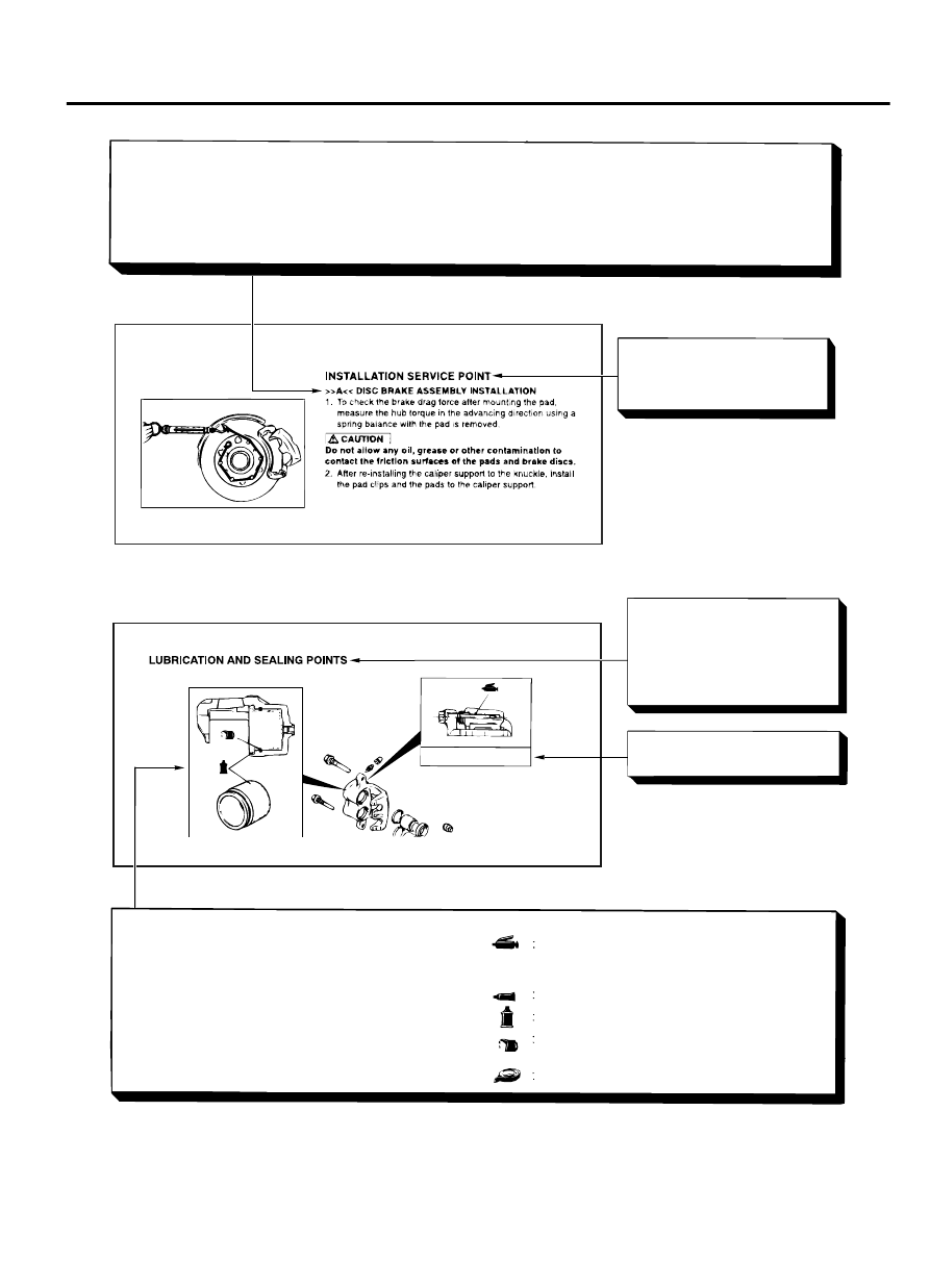
<<A>> : Indicates that there are essential points for removal or disassembly.
>>A<< : Indicates that there are essential points for installation or assembly.

Operating procedures,
cautions, etc. on removal,
installation, disassembly and
assembly are described

The title of the page
(following the page on which
the diagram of component
parts is presented) indicating
the locations of lubrication and
sealing procedures.

Indicates (by symbols) where
lubrication is necessary.

Symbols for lubrication, sealants and adhesives

Symbols are used to show the locations for lubrication
and for application of sealants and adhesives.   
These symbols are included in the diagram of  
component parts or on the page following the  
component parts page. The symbols do not always  
have accompanying text to support that symbol.   

Adhesive tape or butyl rubber tape

Grease
  (Multi-purpose grease unless there is a
  brand or type specified)

Sealant or adhesive
Brake fluid or automatic transmission fluid

Engine oil, gear oil or air conditioning  
compressor oil

Grease: repair kit grease

ZC6012880000

GENERAL <BODY AND CHASSIS>

00-5

HOW TO USE THIS MANUAL

TROUBLESHOOTING GUIDELINES

M10001000088USA0000010001

VERIFY THE COMPLAINT

Make sure the customer's complaint and the service
writer's  work  order  description  are  understood
before starting work.

Make  sure  the  correct  operation  of  the  system  is
understood. Read the service manual description to
verify normal system operation.

Operate the system to see the symptoms. Look for
other  symptoms  that  were  not  reported  by  the
customer, or on the work order, that may be related
to the problem.

DETERMINE POSSIBLE CAUSES

Compare the confirmed symptoms to the diagnostic
symptom  indexes  to  find  the  right  diagnosis
procedure.
If the confirmed symptoms cannot be found on any
symptom index, determine other possible causes.

Analyze the system diagrams and list all possible
causes for the problem symptoms.

Rank  all  these  possible  causes  in  order  of
probability, based on how much of the system they
cover, how likely they are to be the cause, and how
easy  they  will  be  to  check.  Be  sure  to  take
experience  into  account.  Consider  the  causes  of
similar problems seen in the past. The list of causes
should be ranked in order from general to specific,
from  most-likely  to  least-likely,  and  from  easy-to-
check to hard-to-check.

FIND THE PROBLEM

After  the  symptoms  have  been  confirmed,  and
probable causes have been identified, the next step

is  to  make  step-by-step  checks  of  the  suspected
system  components,  junctions,  and  links  in  logical
order.
Use the diagnostic procedures in the service manual
whenever possible. Follow these procedures carefully
to  avoid  missing  an  important  step  in  the  diagnosis
sequence. It might be the skipped step that leads to
the solution of the problem.
If  the  service  manual  doesn't  have  step-by-step
procedures  to  help  diagnose  the  problem,  make  a
series of checks based on the ranked list of probable
causes. Troubleshooting checks should be made in
the order that the list of causes was ranked:

general to specific

most-likely to least-likely

easy-to-check to hard-to-check

REPAIR THE PROBLEM

When the step-by-step troubleshooting checks find a
fault, perform the proper repairs. Make sure to fix the
root cause of the problem, not just the symptom. Just
fixing the symptom, without fixing the root cause, will
cause the symptom to eventually return.

VERIFY THE REPAIR

After repairs are made, recheck the operation of the
system to confirm that the problem is eliminated. Be
sure to check the system thoroughly. Sometimes new
problems are revealed after repairs have been made.

HOW TO USE TROUBLESHOOTING/INSPECTION SERVICE POINTS

TROUBLESHOOTING CONTENTS

M10001000133USA0000010001

The  SRS-ECU  adopts  the  rollover  specification
that the curtain airbag and seat belt pre-tensioner
operate at the occurrence of rollover. Therefore,
do not tilt the vehicle to the right and left with the
IG ON or tilt the SRS-ECU to the right and left with
the IG ON and the harness installed.

During  diagnosis,  a  diagnostic  trouble  code
associated with other system may be set when the

00-6

GENERAL <BODY AND CHASSIS>

TROUBLESHOOTING GUIDELINES

ignition switch is turned "ON" with connector(s)
disconnected.  On  completion,  confirm  all
systems  for  diagnostic  trouble  code(s).  If
diagnostic trouble code(s) are set, erase them all.

Since the radiator fan rotates during CAN bus line
diagnostics,  make  sure  that  no  one  is  servicing
the  engine  compartment  before  diagnosing  the
CAN  bus  line.  Since  the  CAN  communication

stops  when  diagnosing  the  CAN  bus  line,  the
ETACS-ECU  detects  the  time-out  of  the  engine
control module, and activates the radiator fan to
prevent overheating as fail-safe.
Troubleshooting  of  electronic  control  systems  for
which scan tool MB991958 can be used follows the
basic  outline  described  below.  Even  in  systems  for
which scan tool MB991958 cannot be used, some of
these systems still follow this outline.

1. STANDARD FLOW OF DIAGNOSTIC TROUBLESHOOTING

Troubleshooting sections are based on the diagnostic
flow as below. If the diagnostic flow is different from
that  given  below,  or  if  additional  explanation  is

required, the details of such differences or additions
will also be listed.

Diagnostic method

ZC604018

Gathering information
from the customer. 

Check trouble symptom.

Reoccurs

Does not reoccur

CAN bus diagnosis chart*

  CAN bus diagnosis*

Read the diagnosis code.

Read the diagnosis code.

After taking note of the 
malfunction code, erase the
diagnosis code memory.

Recheck trouble symptom.

Read the diagnosis codes.

How to treat past 
trouble*

Refer to the INSPECTION CHA RT
FOR DI AGNOSIS CODES  
(Re fer to applica ble g roup) .

How to treat past 
trouble*

Refer to the INSPECTION CHA RT
FOR T ROUBLE SYMP TOMS  
(Re fer to applica ble g roup) .

INTERMITTENT MALFUNCTIONS

*

Diagnosis code
displayed.
(Current trouble)*

Diagnosis code
displayed.
(Current trouble)*

No diagnosis
code.

No diagnosis
code.

Diagnosis code
displayed.
(Past trouble)*

Diagnosis code
displayed.
(Past trouble)*

No diagnosis  
code or  
communication
with scan tool  
MB991958 not
possible

Diagnosis code
displayed.

OK

NG

2

1

3

3

3

3

4

4

5

Coding data check*

6

0000

*1:  For  how  to  diagnose  CAN  bus  lines,  refer  to
GROUP 54D P.54D-10.

*2:  For  the  CAN  bus  diagnosis  chart,  refer  to
GROUP 54D P.54D-17.

GENERAL <BODY AND CHASSIS>

00-7

HOW TO USE TROUBLESHOOTING/INSPECTION SERVICE POINTS

*3: When scan tool MB991958 detects a diagnostic
trouble  code,  its  display  informs  users  whether  a
mechanical  problem  currently  exists  or  whether  it
existed before. The message for the former state
identifies it as an "Active" and the message for the
latter identifies it as a "Stored".

*4:  For  how  to  treat  past  trouble,  refer  to  P.
00-17.

*5: For how to cope with intermittent malfunctions,
refer to P.00-15.

*6: For coding data, refer to P.00-34.

2. SYSTEM OPERATION AND SYMPTOM

VERIFICATION TESTS

If verification of the symptom(s) is difficult, procedures
for  checking  operation  and  verifying  symptoms  are
shown.

3. DIAGNOSTIC FUNCTION

The following trouble code diagnosis are shown.

How to read diagnostic trouble codes

How to erase diagnostic trouble codes

Input inspection service points

4. DIAGNOSTIC TROUBLE CODE CHART

If the scan tool displays a diagnostic trouble code, find
the applicable inspection procedure according to this
chart.

5. SYMPTOM CHART

If  there  are  symptoms,  even  though  the  scan  tools
show that no DTCs are set, inspection procedures for
each symptom will be found by using this chart.

6. DIAGNOSTIC TROUBLE CODE

PROCEDURES

Indicates the inspection procedures corresponding to
each diagnostic trouble code. (Refer to P.00-9).

7. SYMPTOM PROCEDURES

Indicates the inspection procedures corresponding to
each  symptom  listed  in  the  Symptom  Chart.  (Refer
to P.00-9).

8. SERVICE DATA REFERENCE TABLE

Inspection  items  and  normal  judgment  values  have
been provided in this chart as reference information.

9. CHECK AT ECU TERMINALS

Terminal numbers for the ECU connectors, inspection
items, and standard values have been provided in this
chart as reference information.

TERMINAL VOLTAGE CHECKS

1.

Connect a needle-nosed wire probe to a voltmeter
probe.

Short-circuiting the positive (+) probe between a
connector terminal and ground could damage the
vehicle wiring, the sensor, the ECU, or all three.
Use care to prevent this!

2.

Insert the needle-nosed wire probe into each of the
ECU  connector  terminals  from  the  wire  side,  and
measure  the  voltage  while  referring  to  the  check
chart.

NOTE: 

Measure voltage with the ECU connectors

connected.You may find it convenient to pull out
the ECU to make it easier to reach the connector
terminals.Checks don't have to be carried out in
the order given in the chart.

3.

If  voltage  readings  differ  from  normal  condition
values,  check  related  sensors,  actuators,  and
wiring. Replace or repair as needed.

4.

After  repair  or  replacement,  recheck  with  the
voltmeter  to  confirm  that  the  repair  has  corrected
the problem.

TERMINAL RESISTANCE AND CONTINUITY
CHECKS

1.

Turn  the  ignition  switch  to  the  "LOCK"  (OFF)
position.

2.

Disconnect the ECU connector.

If resistance and continuity checks are performed
on  the  wrong  terminals,  damage  to  the  vehicle
wiring,  sensors,  ECU,  and/or  ohmmeter  may
occur. Use care to prevent this!

3.

Measure  the  resistance  and  check  for  continuity
between  the  terminals  of  the  ECU  harness-side
connector while referring to the check chart.

NOTE: 

Checks don't have to be carried out in

the order given in the chart.

4.

If  the  ohmmeter  shows  any  deviation  from  the
Normal Condition value, check the corresponding
sensor, actuator and related electrical wiring, then
repair or replace.

5.

After  repair  or  replacement,  recheck  with  the
ohmmeter to confirm that the repair has corrected
the problem.

00-8

GENERAL <BODY AND CHASSIS>

HOW TO USE TROUBLESHOOTING/INSPECTION SERVICE POINTS


Content   ..  47  48  49  50   ..