Mitsubishi Outlander XL. Manual - part 42


  Index      Mitsubishi     Mitsubishi Outlander XL - service repair manual 2007 year


Search            


Content   ..  40  41  42  43   ..


Mitsubishi Outlander XL. Manual - part 42


Alternately  repeat  hammering  and  filing  until  there  are  file
traces over the entire repair area.

6.

Make a solder build-up at the repair.

7.

Finally, finish up the solder build-up using a body file.

USING A FRAME STRAIGHTENER

M40900000130USA0000010000

For serious and extensive damage, when for example
the  damage  extends  to  the  frame  of  members,  it  is
necessary to first use a frame straightener to make a
rough, overall repair of the body, and then to proceed
to careful repairs of each individual area of damage.
When a frame straightener is used for body repairs, it
is a fundamental principle that the pulling should be in
the  direction  from  which  the  impact  was  sustained,
and from the opposite direction. If this is, in error, not
done,  previously  undamaged  components  will  be
deformed, and repair may become impossible.
It is for that reason that it is important to decide upon
the method of repair, especially regarding the initial
overall repair, by following the steps below.

OVERALL ROUGH REPAIRS

1.

First, analyze the impact. This means analysis and
consideration of the point of collision, the speed at
the time of collision, and the strength, weight and
shape of the object hit.

2.

Then get a complete understanding of the condition
of the existing damage. In particular, if the damage
extends to the suspension installation components,
an inspection must be made to determine whether

or not there is any deviation of the frame or body
alignment.

3.

Finally, determine what repair methods should be
used.

To  what  extent  will  frame  straightening  and  other
overall repairs be necessary in order to restore the
damaged areas to the way they were?

At what stage of the repairs should panels adjoining
the components to be frame straightened, etc., be
removed?

Decide  upon  the  work  steps  and  restoration
methods  to  be  followed  after  the  rough,  overall
repairs are completed.

Select the frame straightener based upon the results
of above, and use it to pull in the appropriate direction.
More  than  one  direction  may  be  appropriate,
depending upon the damage.
If the damage is of a moderate degree or less, it may
be possible to do all that is necessary in one pull.
If,  however,  the  damage  is  major,  that  is  to  say  if
repairs  must  be  made  to  components  of  the
passenger compartment such as the dash panel, etc.,
it may be necessary, after completing the first pull, to
set  up  the  frame  straightener  at  a  different  position
and use it again at that position.

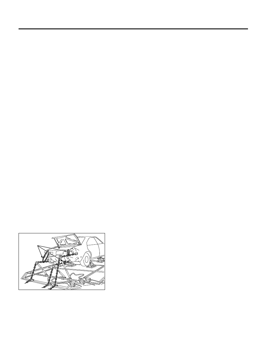
FRAME STRAIGHTENING NOTES

ZB6002470000

Wires for
protection

For safety, no one must be standing in the direction of the pull.

Wires or chains should be used for protection in the event of
an accident.

For frame straightening of body with frame, care should be
taken regarding the position (body mount) of installation to the
frame.  The  reason  for  this  is  that  usually  mounting  rubber
pieces  are  used  at  the  installation  part  in  order  to  improve
vibration prevention, and these mounting rubber pieces might
be deformed if there is a deviation of the installation position.

BASE OF BODY REPAIR

9-27

BODY REPAIR

If the part to be pulled is made of high-tensile steel (which has
a higher tensional strength and yield point than ordinary steel),
the pulling must be done with care in order to avoid "over pull"
and "spring back". It is particularly important for the pulling of
sidemembers and other reinforcement components made of
high-tensile steel that the pulling not be all done at one time;
pull gradually while using a hammer to repair distorted areas
as the pulling is done.

FRAME REPAIR PROCEDURES

M40900000140USA0000010000

The frame is subjected to the following types of loads.

Vertical loads: Vertical loads may occur either while
stopped or during travel.

Lateral (horizontal) loads: This type of loads occurs
during turning, start-off and braking.

Torsional  loads:  Torsional  loads  occur  while
traveling on roads with poor surface conditions.

These various types of loads are compounded under
various conditions, and are applied to the frame.
As a result, it is important, before attempting to repair
the  frame,  to  carefully  observe  the  shape  of  the
damaged part and to in that way fully understand the
cause of the damage.

CHECKING FOR FRAME CRACKING OR FLAKING

ZB6002480000

Test hammer

Sidemember

Check, by using a test hammer, for flaking or cracking of the
welded  surface  of  the  sidemembers,  crossmembers  and
brackets.

REPAIRING CRACKS

If the check reveals a crack(s) in the frame, repair as described
bellow.

ZB600249

Crack-stop hole

Crack

A

A

Ø6 – 8 mm
(0.2 – 0.3 in)

A : 7 – 8 mm (0.3 in)

0000

1.

Remove the components near the crack.

2.

Make  Φ  6  -  8  mm  (0.2  -  0.3  inch)  holes  (to  prevent  further
cracking), by using a drill, at points 7 - 8 mm (0.3 inch) from
the crack ends.

9-28

BASE OF BODY REPAIR

BODY REPAIR

ZB6002500000

Ø10 – 12 mm
(0.4 – 0.5 in)

Ø10 

 12 mm (0.4 

 0.5 in)

Ø6 

 8 mm 

(0.2 

 0.3 in)

3.

Use a Φ 10 - 12 mm (0.4 - 0.5 inch) drill to bevel the hole
openings.

ZB6002510000

Crack

Crack-sto p
hole

Appr ox.
8 mm
(0.3 in)

 Appr ox.
   1 mm 
   (0.04 in)

Appr ox.
1 mm 
(00.4 in)

Appr ox.

90°

If a chisel
is used

If a gouge
is used

A

A

A

4.

Use a chisel or gouging tool to open up the crack and holes,
and then fill the crack and holes by MIG welding.

ZB6002520000

Gas welding should be avoided because it causes thermal
distortion of the frame.

When using a grinder for finishing, be careful not to grind
the frame excessively.

5.

Using a grinder for finishing after welding.

ZB600253

A

A

A : 30 – 45°

0000

The  reinforcement  plate  should  completely  cover  the
cracked part.

The  reinforcement  plate  should  be  the  same  thickness
and material as the frame.

6.

To avoid a concentration of stress, prepare a reinforcement
plate that has been cut to 30 - 45 degree angle at both ends.

ZB600254

10 mm (0.4 in)

Welded point

0000

Be sure that the edges of the reinforcement plate are not
near  any  place  where  a  concentration  of  stress  of  the
crossmember or spring hanger installation part, etc. could
easily occur.

7.

Attach the reinforcement plate to the repaired crack area by
MIG welding. In order to avoid a concentration of stress at the
time, weld the reinforcement plate at points about 10 mm (0.4
inch) from its edges.

BASE OF BODY REPAIR

9-29

BODY REPAIR

ZB6002550000

(2)

(1)

NOTE: 

If the crack is at the upper side of the frame,

attach the reinforcement plate facing downward, as shown in
(1).If the crack is at the lower side, attach the
reinforcement plate to face upward, as shown in (2).

8.

Finally, apply a coating of chassis black to the repaired area
and to any places where the coating has flaked off.

NOTES REGARDING REPAIR WORK

M40900000150USA0000010000

SAFETY MEASURES

1

4

5

6

7

8

9

10

11

2

3

ZB6002560000

PROTECTIVE GEAR
During  body  repair  work,  a  work  suit,  a  work  cap,  and  safety
shoes should be worn at all times. Depending on the work being
done, safety glasses, gloves, ear protectors, a dustproof mask,
etc., should also be worn as needed.

1.

Safety glasses

2.

Work cap

3.

Ear protectors

4.

Head protector

5.

Work suit

6.

Dustproof mask

7.

Work apron

8.

Welding gloves

9-30

BASE OF BODY REPAIR

BODY REPAIR


Content   ..  40  41  42  43   ..