Mitsubishi Outlander GS45X. Manual - part 912
MULTIPORT FUEL INJECTION (MFI) DIAGNOSIS
TSB Revision
MULTIPORT FUEL INJECTION (MFI) <3.0L ENGINE>
13B-581
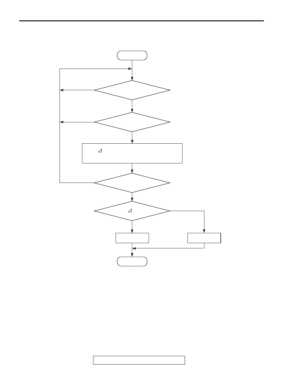
DTC SET CONDITIONS
Logic Flow Chart
.
Check Conditions
• Under the ignition timing retard control.
• Engine coolant temperature is between 7°C
(45
°F) and 41°C (106°F).
Judgement Criteria
• For 10 seconds, the difference between the basic
ignition timing and the target/specified ignition
timing is 3
°CA or less on average during the
retard control.
.
OBD-II DRIVE CYCLE PATTERN
Refer to Diagnostic Function
− OBD-II Drive Cycle −
Pattern 23
.
TROUBLESHOOTING HINTS (The most
likely causes for this code to be set are:)
• Dirtiness around throttle valve.
• ECM failed.
End
No
No
Malfunction
Good
Average
θ <= 3˚CA
AK604371
Start
Yes
Yes
Yes
Yes
Monitoring
conditions
10secs have passed
Ignition timing retard
control status ON
θ = Base ignition timing -
commanded ignition timing
No
No