Mitsubishi Outlander GS45X. Manual - part 910


  Index      Mitsubishi     Mitsubishi Outlander GS45X - service repair manual


Search            


Content   ..  908  909  910  911   ..


Mitsubishi Outlander GS45X. Manual - part 910


MULTIPORT FUEL INJECTION (MFI) DIAGNOSIS

TSB Revision

MULTIPORT FUEL INJECTION (MFI) <3.0L ENGINE>

13B-573

DIAGNOSIS

Required Special Tools:

• MB991958: Scan tool (M.U.T.-III Sub Assembly)

• MB991824: V.C.I.

• MB991827: USB Cable

• MB991910: Main Harness A

• MB991658: Test Harness Set

STEP 1. Check harness connector B-12 at EGR valve and 
harness connector B-10 at ECM for damage.
Q: Is the harness connector in good condition?

YES : Go to Step 2.
NO :  Repair or replace it. Refer to GROUP 00E, Harness 

Connector Inspection 

P.00E-2

. Then go to Step 5.

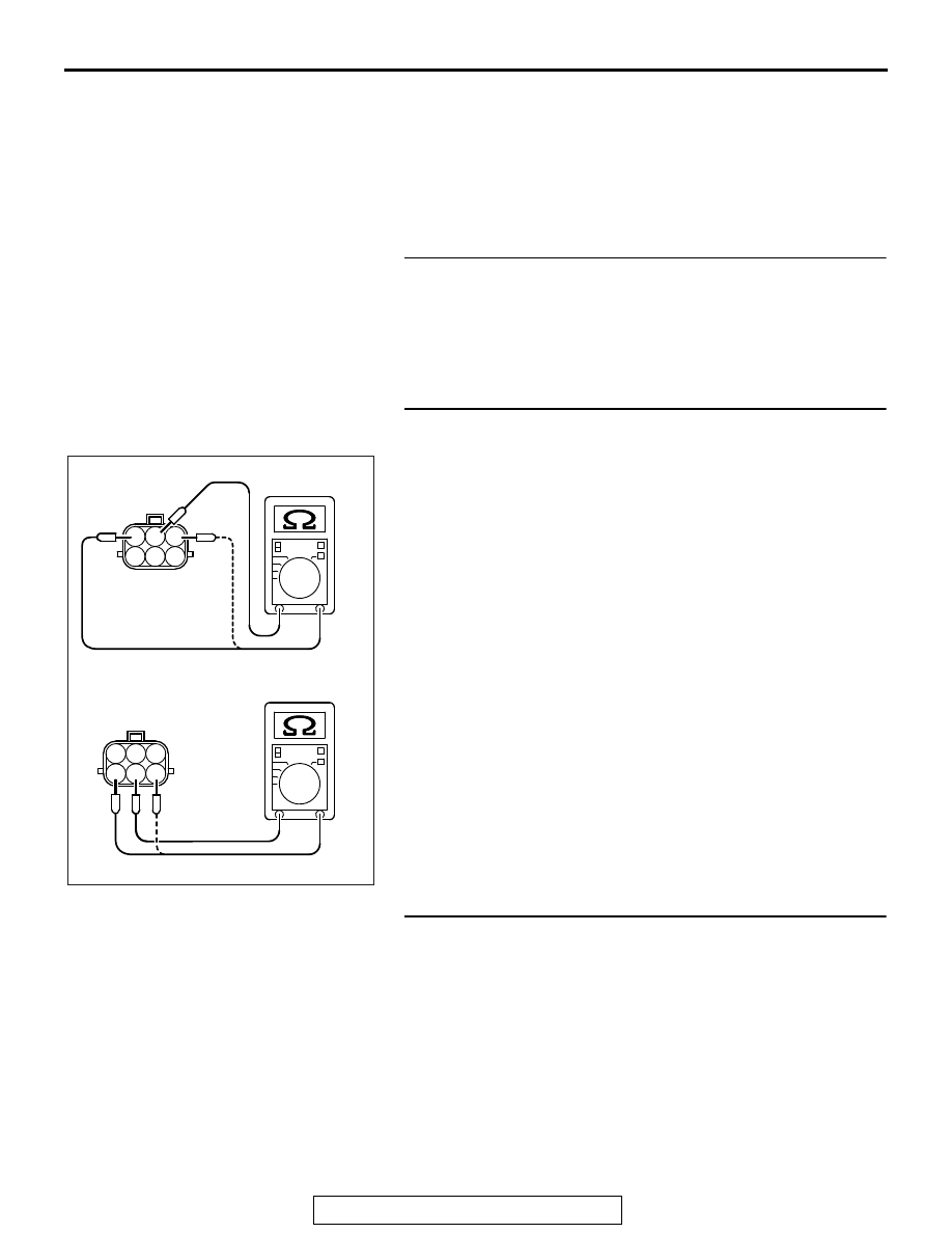
STEP 2. Measure the EGR valve motor coil resistance.
(1) Disconnect the EGR valve connector B-12.
(2) Measure the resistance between EGR valve connector 

terminal No. 2 and either terminal No. 1 or terminal No. 3.

Standard value: 20 

 24 Ω [at 20°C (68°F)]

(3) Measure the resistance between EGR valve connector 

terminal No. 5 and either terminal No. 4 or terminal No. 6.

Standard value: 20 

 24 Ω [at 20°C (68°F)]

Q: Is the measured resistance between 20 and 24 ohms [at 

20

°C (68°F)]?

YES : Go to Step 3.
NO :  Replace the EGR valve. Then go to Step 5.

STEP 3. Check for short circuit to power supply between 
EGR valve connector B-12 and ECM connector B-10.
Q: Is the harness wire in good condition?

YES : Then go to Step 4.
NO :  Repair it. Then go to Step 5.

1

2 3

3

4

5 6

1

2 3

4

5 6

AK700535

MULTIPORT FUEL INJECTION (MFI) DIAGNOSIS

TSB Revision

MULTIPORT FUEL INJECTION (MFI) <3.0L ENGINE>

13B-574

STEP 4. Check the EGR valve operation using special tool 
MB991658.
(1) Remove the EGR valve.
(2) Connect special tool MB991658 to the EGR valve. (All 

terminals should be connected.)

(3) Use the jumper wires to connect terminal No. 2 of the EGR 

valve connector to the positive battery terminal.

(4) Check to ensure that the motor operates when the terminal 

No. 1 and No. 3 of the EGR valve connector are 
respectively connected to the negative battery terminal 
using a jumper wire.

• Vibration should be present at each application of volt-

age to test clip combination.

(5) Then, use jumper wires to connect the terminal No. 5 of the 

EGR valve connector to the positive battery terminal.

(6) Check to ensure that the motor operates when terminal No. 

4 and No. 6 of the EGR valve connector are respectively 
connected to the negative battery terminal using a jumper 
wire.

• Vibration should be present at each application of volt-

age to test clip combination.

(7) Reinstall the EGR valve, using a new gasket, and tighten to 

the specified torque.

Tighten torque: 23 

± 6 Nm [17 ± 4 ftIb]

Q: Is the EGR valve operating properly?

YES : Replace the ECM. When the ECM is replaced, 

register the ID code. Refer to GROUP 42B, Diagnosis 
− ID Codes Registration Judgment Table <Vehicles 

with KOS> 

P.42B-15

 or GROUP 42C, Diagnosis 

− ID 

Codes Registration Judgment Table <Vehicles with 
WCM> 

P.42C-10

. Then go to Step 5.

NO :  Replace the EGR valve. Then go to Step 5.

STEP 5. Test the OBD-II drive cycle.
(1) Carry out a test drive with the drive cycle pattern. Refer to 

Diagnostic Function 

− OBD-II Drive Cycle − Pattern 3 

P.13B-11

.

(2) Check the diagnostic trouble code (DTC).
Q: Is DTC P0490 set?

YES : Retry the troubleshooting.
NO :  The inspection is complete.

DTC P0506: Idle Control Sytem RPM Lower Than Expected

.

TECHNICAL DESCRIPTION

• The amount of air taken in during idling is regu-

lated by the opening and closing of the throttle 
valve.

• The ECM checks the difference between the 

actual engine speed and the target engine speed.

.

DESCRIPTIONS OF MONITOR METHODS

Difference between actual and target idle speed is 
over the specified value.

.

AK700068

MB991658

Battery

AB

MULTIPORT FUEL INJECTION (MFI) DIAGNOSIS

TSB Revision

MULTIPORT FUEL INJECTION (MFI) <3.0L ENGINE>

13B-575

MONITOR EXECUTION

Continuous

.

MONITOR EXECUTION CONDITIONS 
(Other monitor and Sensor)

Other Monitor (There is no temporary DTC stored 

in memory for the item monitored below)

• Misfire monitor

• Exhaust gas recirculation (EGR) system monitor

• Fuel system monitor

Sensor (The sensor below is determined to be 

normal)

• Mass airflow sensor

• Engine coolant temperature sensor

• Intake air temperature sensor

• Barometric pressure sensor

• Throttle position sensor

.

DTC SET CONDITIONS

Logic Flow Chart

.

Check Conditions

• Under the closed loop idle speed control.

• The engine coolant temperature is more than 

41

°C (105°F).

• Battery positive voltage is higher than 10 volts.

• Barometric pressure is higher than 76 kPa (22.4 

in.Hg).

• Intake air temperature is higher than −10°C 

(14

°F).

• 3 seconds have elapsed from the start of the pre-

vious monitoring.

• Target air flow rate is more than 33 g/sec (28 

L/sec).

Good

Malfunction

Calculated    Ne

End

No

No

No

AK604345

 Ne < -100 r/min

or > 200 r/min

Have 10secs passed?

Ne = (actual-Ne) - (target-Ne)

Ne:  engine speed

Start

Yes

Yes

Yes

Monitoring
conditions

MULTIPORT FUEL INJECTION (MFI) DIAGNOSIS

TSB Revision

MULTIPORT FUEL INJECTION (MFI) <3.0L ENGINE>

13B-576

Judgement Criterion

• The actual idle speed is less than the target idle 

speed by 100 r/min or more for 10 seconds.

.

OBD-II DRIVE CYCLE PATTERN

Refer to Diagnostic Function 

− OBD-II Drive Cycle − 

Pattern 18 

P.13B-11

.

.

TROUBLESHOOTING HINTS (The most 
likely causes for this code to be set are:)

• Throttle valve area is dirty.

DIAGNOSIS

Required Special Tools:

• MB991958: Scan Tool (M.U.T.-III Sub Assembly)

• MB991824: V.C.I.

• MB991827: USB Cable

• MB991910: Main Harness A

STEP 1. Using scan tool MB991958, read the diagnostic 
trouble code (DTC)

CAUTION

To prevent damage to scan tool MB991958, always turn the 
ignition switch to the "LOCK" (OFF) position before con-
necting or disconnecting scan tool MB991958.
(1) Connect scan tool MB991958 to the data link connector.
(2) Turn the ignition switch to the "ON" position.
(3) After the DTC has been deleted, read the DTC again.
(4) Turn the ignition switch to the "LOCK" (OFF) position.
Q: Is the diagnostic trouble code other than P0506 set?

YES : Refer to Diagnostic Trouble Code Chart 

P.13B-50

.

NO :  Go to Step 2.

STEP 2. Check the throttle body. (throttle valve area)
Q: Is the throttle valve area dirty?

YES : Perform cleaning. Refer to Throttle Body (Throttle 

Valve Area) Cleaning 

P.13B-882

. Then go to Step 4.

NO :  Go to Step 3.

AK700568AB

MB991824

MB991827

MB991910

Data link
connector


Content   ..  908  909  910  911   ..