Mitsubishi Outlander GS45X. Manual - part 909


  Index      Mitsubishi     Mitsubishi Outlander GS45X - service repair manual


Search            


Content   ..  907  908  909  910   ..


Mitsubishi Outlander GS45X. Manual - part 909


MULTIPORT FUEL INJECTION (MFI) DIAGNOSIS

TSB Revision

MULTIPORT FUEL INJECTION (MFI) <3.0L ENGINE>

13B-569

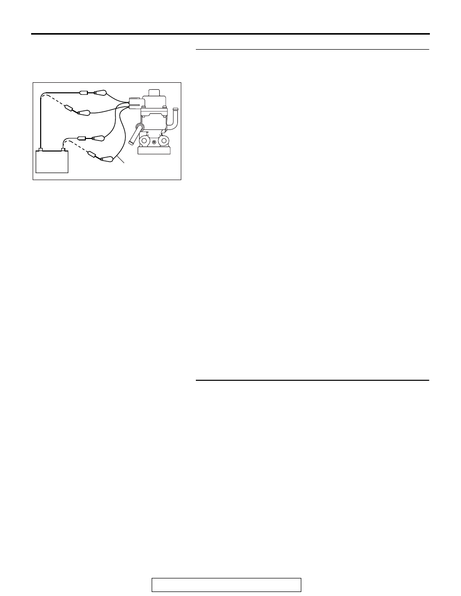
STEP 5. Check the EGR valve operation using special tool 
MB991658.
(1) Remove the EGR valve.
(2) Connect special tool MB991658 to the EGR valve. (All 

terminals should be connected.)

(3) Use the jumper wires to connect terminal No. 2 of the EGR 

valve connector to the positive battery terminal.

(4) Check to ensure that the motor operates when the terminal 

No. 1 and No. 3 of the EGR valve connector are 
respectively connected to the negative battery terminal 
using a jumper wire.

• Vibration should be present at each application of volt-

age to test clip combination.

(5) Then, use jumper wires to connect the terminal No. 5 of the 

EGR valve connector to the positive battery terminal.

(6) Check to ensure that the motor operates when terminal No. 

4 and No. 6 of the EGR valve connector are respectively 
connected to the negative battery terminal using a jumper 
wire.

• Vibration should be present at each application of volt-

age to test clip combination.

(7) Reinstall the EGR valve, using a new gasket, and tighten to 

the specified torque.

Tighten torque: 23 

± 6 Nm [17 ± 4 ftIb]

Q: Is the EGR valve operating properly?

YES : Replace the ECM. When the ECM is replaced, 

register the ID code. Refer to GROUP 42B, Diagnosis 
− ID Codes Registration Judgment Table <Vehicles 

with KOS> 

P.42B-15

 or GROUP 42C, Diagnosis 

− ID 

Codes Registration Judgment Table <Vehicles with 
WCM> 

P.42C-10

.

NO :  Replace the EGR valve. Then go to Step 6.

STEP 6. Test the OBD-II drive cycle.
(1) Carry out a test drive with the drive cycle pattern. Refer to 

Diagnostic Function 

− OBD-II Drive Cycle − Pattern 3 

P.13B-11

.

(2) Check the diagnostic trouble code (DTC).
Q: Is DTC P0489 set?

YES : Retry the troubleshooting.
NO :  The inspection is complete.

AK700068

MB991658

Battery

AB

MULTIPORT FUEL INJECTION (MFI) DIAGNOSIS

TSB Revision

MULTIPORT FUEL INJECTION (MFI) <3.0L ENGINE>

13B-570

DTC P0490: EGR Value (Stepper Motor) Circuit Malfunction (Battery Short) 

1

2 3

4

5 6

AK700165

1

2

3 4 5 6 7 8 9 10 11 12 13 14 15 16

17 18 19 20 21 22 23 24 25 26 27 28 29 30 31 32

33 34 35 36 37 38 39 40 41 42 43 44 45 46 47 48

49 50 51 52 53 54 55 56 57 58 59 60 61 62 63 64

1

3

2

4

1

10 111213 14 1516 17 1819 20

2 3 4

5 6 7 8 9

1

3

4

6

31

32

47

48

B-12

(MU802056)

B-10

20A

WHITE

WHITE

WHITE

WHITE

RED

GRA

Y

-BLUE

SKY BLUE

LIGHT GREEN

WHITE

A-33X

4

3

1

2

22

OFF

ON

AB

EGR VALVE CIRCUIT

EXHAUST GAS
RECIRCULATION
(EGR) VALVE

36

FUSIBLE LINK

4

2

5

A-13

RELAY BOX
(ENGINE COMPARTMENT)

TO ECM

ENGINE CONTROL MODULE

MFI
RELAY

MULTIPORT FUEL INJECTION (MFI) DIAGNOSIS

TSB Revision

MULTIPORT FUEL INJECTION (MFI) <3.0L ENGINE>

13B-571

.

CIRCUIT OPERATION

• The EGR valve power is supplied from the MFI 

relay (terminal No. 2).

• The ECM (terminals No. 31, No. 32, No. 47, No. 

48) drives the stepper motor by sequentially turn-
ing "ON" the power transistors in the ECM and 
providing ground to the EGR valve (terminal No. 
1, No. 3, No. 4, No. 6).

.

TECHNICAL DESCRIPTION

The ECM checks whether a short circuit to the power 
supply exists or not by measuring the EGR valve 
(stepper motor) drive circuit voltage when the current 
not flowing through the coils of the EGR valve (step-
per motor).

.

DESCRIPTIONS OF MONITOR METHODS

When the EGR valve (stepper motor) drive circuit 
voltage is over the specified range, it is judged that a 
malfunction exists.

.

MONITOR EXECUTION

Continuous

.

MONITOR EXECUTION CONDITIONS 
(Other monitor and Sensor)

Other Monitor (There is no temporary DTC stored 

in memory for the item monitored below)

• EGR stepper motor monitor

Sensor (The sensor below is determined to be 

normal)

• Mass airflow sensor

• Engine coolant temperature sensor

• Intake air temperature sensor

• Barometric pressure sensor

• Manifold absolute pressure sensor

• Accelerator pedal position sensor

.

AK700432

AB

Exhaust gas
recirculation valve

B-12 (GR)

Connector: B-12

AK700401AB

ECM

B-10 (GR)

Connector: B-10

AK700399AB

MFI relay

A-33X

Connector: A-33X

AK900602

Connector: A-13

A-13

AB

MULTIPORT FUEL INJECTION (MFI) DIAGNOSIS

TSB Revision

MULTIPORT FUEL INJECTION (MFI) <3.0L ENGINE>

13B-572

DTC SET CONDITIONS
Logic Flow Chart

.

Check Conditions

• Ignition switch is "ON" position.

• Battery positive voltage is at between 10 and 

16.5 volts.

Judgement Criterion

• When the EGR valve is energized, the ECM volt-

age should be 6.7 volts or more for 1.4 seconds.

.

OBD-II DRIVE CYCLE PATTERN

Refer to Diagnostic Function 

− OBD-II Drive Cycle − 

Pattern 3 

P.13B-11

.

.

TROUBLESHOOTING HINTS (The most 
likely causes for this code to be set are: )

• EGR valve (stepper motor) failed.

• Harness damage.

• Connector damage.

• ECM failed.

End

Malfunction

Good

No

No

No

No

No

Stepper motor activation

command ON?

AK900363

Start

Yes

Yes

Yes

Yes

Yes

Continuous

failure for 1.4secs

Monitoring
conditions

Circuit voltage

>

 6.7V

Circuit voltage

< 1.5V


Content   ..  907  908  909  910   ..