Mitsubishi Outlander GS45X. Manual - part 896
MULTIPORT FUEL INJECTION (MFI) DIAGNOSIS
TSB Revision
MULTIPORT FUEL INJECTION (MFI) <3.0L ENGINE>
13B-517
.
CIRCUIT OPERATION
• The ECM (terminal No. 114) supplies a 5-volt ref-
erence signal to the fuel tank differential pressure
sensor (terminal No. 3). The fuel tank differential
pressure sensor (terminal No. 2) is grounded
through the ECM (terminal No. 113).
• The fuel tank differential pressure sensor (termi-
nal No. 1) returns a voltage signal to the ECM
(terminal No. 112) that is proportional to the pres-
sure in the fuel tank.
.
TECHNICAL DESCRIPTION
• The ECM monitors the fuel tank differential pres-
sure sensor output voltage.
• The ECM determines whether the fuel tank differ-
ential pressure sensor signal voltage is within
normal operating parameters.
.
DESCRIPTIONS OF MONITOR METHODS
• Compare purge solenoid status with fuel tank dif-
ferential pressure sensor output voltage.
.
MONITOR EXECUTION
• Continuous.
.
MONITOR EXECUTION CONDITIONS
(OTHER MONITOR AND SENSOR)
Other Monitor (There is no temporary DTC stored
in memory for the item monitored below)
• Evaporative emission purge solenoid monitor
• Evaporative emission ventilation solenoid monitor
• Fuel temperature sensor monitor
• Fuel level sensor monitor
Sensor (The sensors below are determined to be
normal)
• Mass airflow sensor
• Barometric pressure sensor
• Intake air temperature sensor
• Engine coolant temperature sensor
• Accelerator pedal position sensor
.
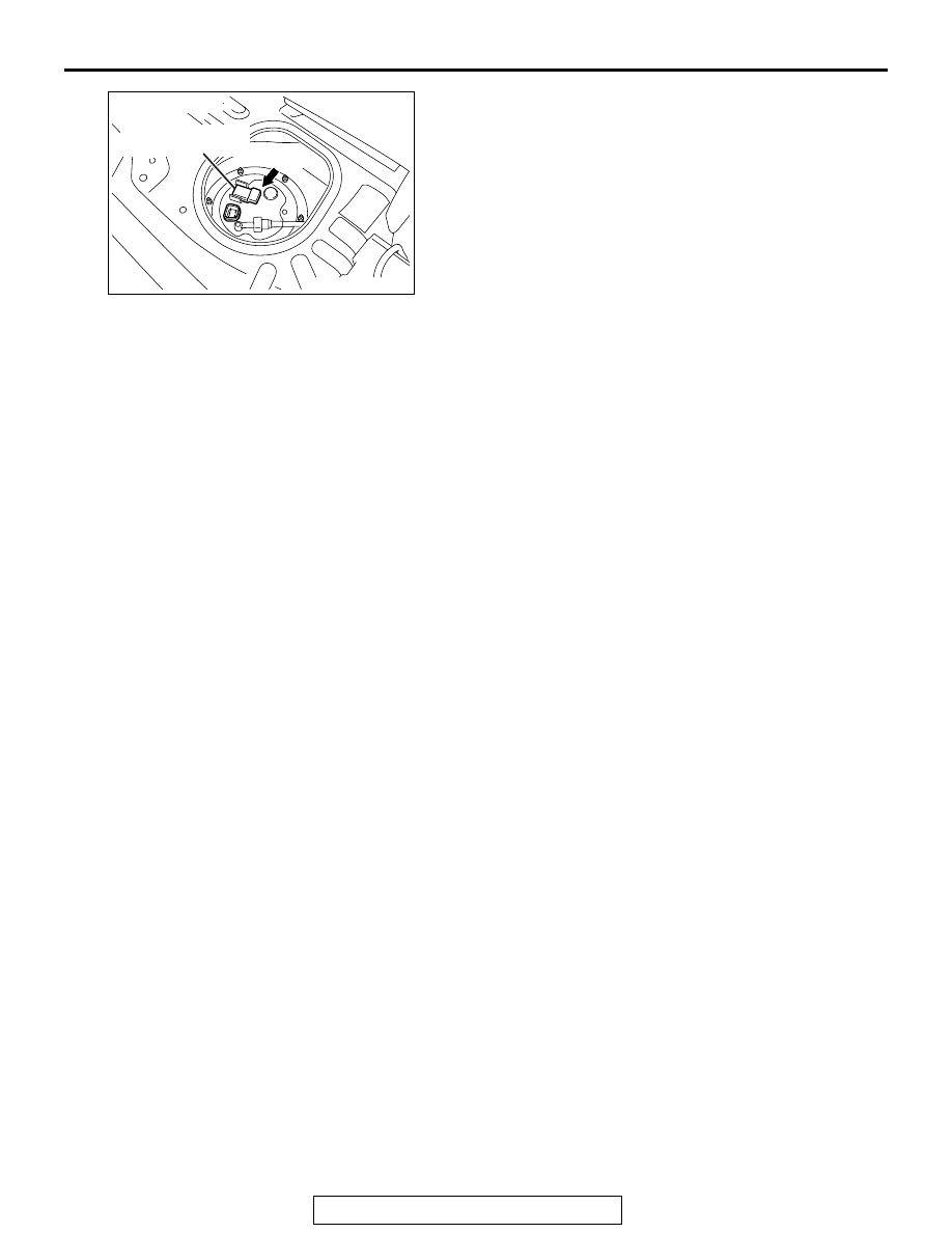
AK704189
Fuel tank differential
pressure sensor
D-19
Connector: D-19
AB