Mitsubishi Outlander GS45X. Manual - part 860


  Index      Mitsubishi     Mitsubishi Outlander GS45X - service repair manual


Search            


Content   ..  858  859  860  861   ..


Mitsubishi Outlander GS45X. Manual - part 860


MULTIPORT FUEL INJECTION (MFI) DIAGNOSIS

TSB Revision

MULTIPORT FUEL INJECTION (MFI) <3.0L ENGINE>

13B-373

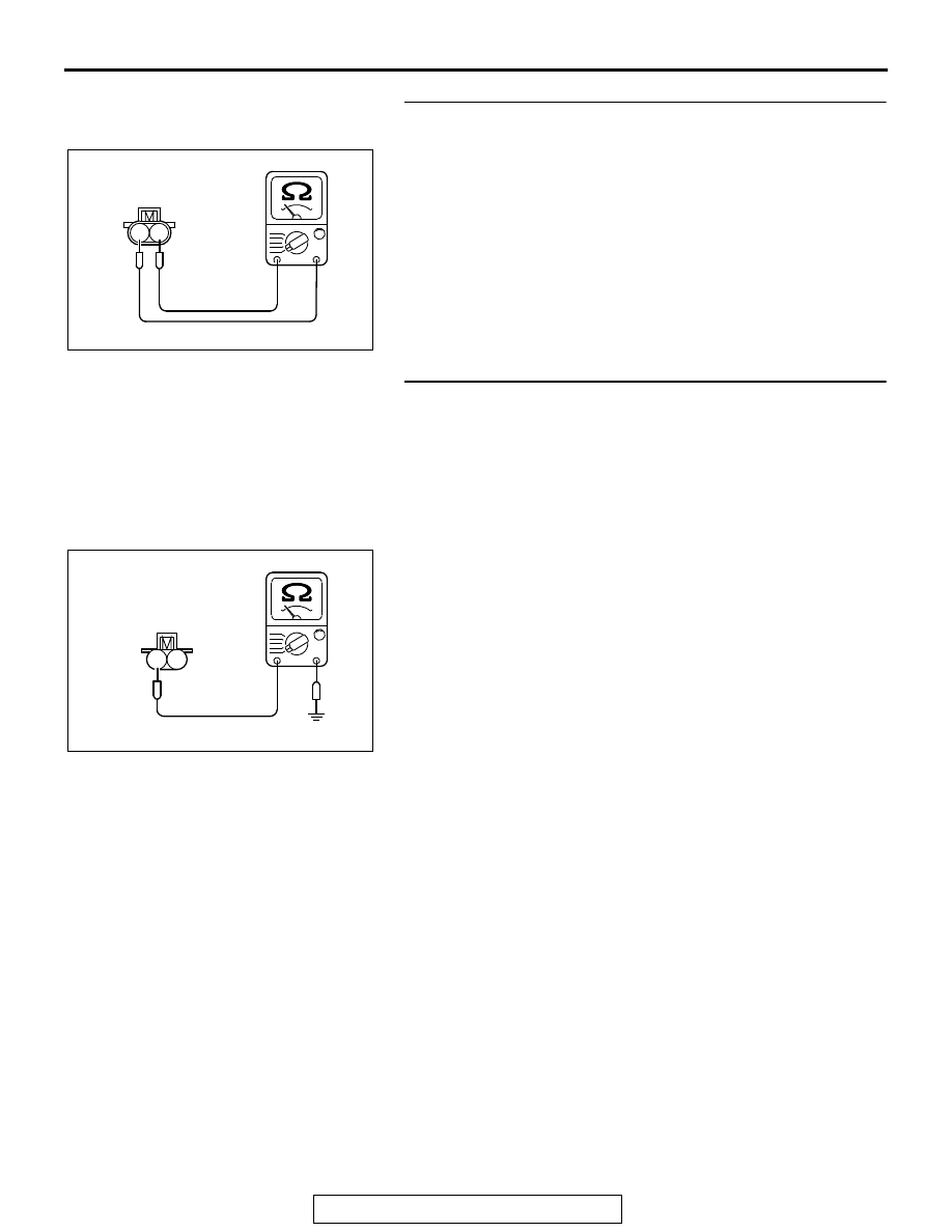
STEP 4. Check the No. 4 cylinder injector.
(1) Disconnect the No. 4 cylinder injector connector B-116.
(2) Measure the resistance between injector side connector 

terminal No. 1 and No. 2.

 Standard value: 10.5 

 13.5 ohms [at 20°C (68°F)]

Q: Is the measured resistance between 10.5 and 13.5 ohms 

[at 20

°C (68°F)]?

YES : Go to Step 5.
NO :  Replace the No. 4 cylinder injector. Then go to Step 7.

STEP 5. Check for harness between the injector connector 
B-116 and the ECM connector B-10.
(1) Disconnect the injector connector B-116 and the ECM 

connector B-10.

(2) Measure the resistance between injector connector B-116 

(terminal No. 2) and the ECM connector B-10 (terminal No. 
19).

• Should be less than 2 ohms.

(3) Measure the continuity between the injector connector 

B-116 (terminal No. 2) and ground.

• Not continuity.

Q: Is the connector wire in good condition?

YES :  Go to Step 6.
NO :  Repair it. Refer to GROUP 00E, Harness Connector 

Inspection 

P.00E-2

. Then go to Step 7.

AK700204

1 2

AB

Injector side
connector

1

2

AK700561 AB

B-116
harness connector:
component side

MULTIPORT FUEL INJECTION (MFI) DIAGNOSIS

TSB Revision

MULTIPORT FUEL INJECTION (MFI) <3.0L ENGINE>

13B-374

STEP 6. Using the oscilloscope, check the No. 4 cylinder 
injector.
(1) Disconnect the No. 4 cylinder injector connector B-116 and 

connect the test harness special tool (MB991658) between 
the separated connectors. (All terminals should be 
connected)

(2) Connect the oscilloscope probe to the injector side 

connector terminal No. 2.
NOTE: When measuring with the ECM side connector, dis-
connect all ECM connectors. Connect the check harness 
special tool (MB992110) between the separated connec-
tors. Then connect an oscilloscope probe to the check har-
ness connector terminal No. 19.

(3) Start the engine and run at idle.

(4) Measure the waveform.

• The waveform should show a normal pattern similar to 

the illustration.

(5) Turn the ignition switch to the "LOCK" (OFF) position.
Q: Is the waveform normal?

YES : It can be assumed that this malfunction is intermittent. 

Refer to GROUP 00, How to Use 
Troubleshooting/Inspection Service Points 

− How to 

Cope with Intermittent Malfunctions 

P.00-15

.

NO :  Replace the ECM. When the ECM is replaced, 

register the ID code. Refer to GROUP 42B, Diagnosis 
− ID Codes Registration Judgment Table <Vehicles 

with KOS> 

P.42B-15

 or GROUP 42C, Diagnosis 

− ID 

Codes Registration Judgment Table <Vehicles with 
WCM> 

P.42C-10

. Then go to Step 7.

STEP 7. Test the OBD-II drive cycle.
(1) Carry out a test drive with the drive cycle pattern. Refer to 

Diagnostic Function 

− OBD-II Drive Cycle − Pattern 22 

P.13B-11

.

(2) Check the diagnostic trouble code (DTC).
Q: Is DTC P0204 set?

YES : Retry the troubleshooting.
NO :  The inspection is complete.

AK700557

1 2

AB

Injector connector

MB991658

Oscilloscope

AK700301

Normal waveform

A: Injector drive time

A

AB

MULTIPORT FUEL INJECTION (MFI) DIAGNOSIS

TSB Revision

MULTIPORT FUEL INJECTION (MFI) <3.0L ENGINE>

13B-375

DTC P0205: Injector Circuit - Cylinder 5

AK700147

1

3

2

4

1

2

3
4

1

2

3 4 5 6 7 8 9 10 11 12 13 14 15 16

17 18 19 20 21 22 23 24 25 26 27 28 29 30 31 32

33 34 35 36 37 38 39 40 41 42 43 44 45 46 47 48

49 50 51 52 53 54 55 56 57 58 59 60 61 62 63 64

1 2 3 4

5 6 7

15

14

13

12

11

9

8

1

6

4

5

9

8

10

10

11

13

15

14

12

16

7

2 3

1

2 3

6

7 8

4 5

9 10

2

1

1

10 111213 14 1516 17 1819 20

2 3 4

5 6 7 8 9

B-104

(MU802062)

B-21

MU802645

1

6

2

50

9

BLUE

B-10

AB

20A

WHITE

WHITE

A-33X

4

3

1

2

22

OFF

ON

WHITE

RED-WHITE

4

1

10

6

7

C-304

C-317

A-13

A-24X

3

BLUE

2

OFF

ON

WHITE

BLUE

BLUE-

YELLO

W

BLUE-

YELLO

W

36

FUSIBLE LINK

ETACS-
ECU

INJECTOR CIRCUIT-CYLINDER 5

BLA

CK

BLA

CK

BLA

CK

IGNITION
SWITCH (IG1)

INJECTOR
RELAY

RELAY BOX
(ENGINE COMPARTMENT)

TO ECM

ENGINE CONTROL MODULE

MFI
RELAY

INJECTOR
NO. 5

MULTIPORT FUEL INJECTION (MFI) DIAGNOSIS

TSB Revision

MULTIPORT FUEL INJECTION (MFI) <3.0L ENGINE>

13B-376

.

CIRCUIT OPERATION

• The injector power is supplied from the injector 

relay (terminal No. 3).

• The ECM controls the injector by turning the 

power transistor in the ECM "ON" and "OFF".

.

TECHNICAL DESCRIPTION

• The amount of fuel injected by the injector is con-

trolled by the amount of continuity time the coil is 
grounded by the ECM.

.

DESCRIPTIONS OF MONITOR METHODS

The ECM detects open circuit and short malfunction.

.

MONITOR EXECUTION

Continuous

.

AK900141 AD

B-104 (GR)

Connector: B-104

AK700399AB

MFI relay

A-33X

Connector: A-33X

AK900134

AD

B-21 (B)

Connector: B-21

Intermediate
connector

AK700413AB

A-24X

Connector: A-24X

Injector relay

AK700401AB

ECM

B-10 (GR)

Connector: B-10

AK700414 AB

ETACS-ECU

C-317

Connectors: C-304, C-317

C-304

AK900602

Connector: A-13

A-13

AB


Content   ..  858  859  860  861   ..