Mitsubishi Outlander GS45X. Manual - part 826
MULTIPORT FUEL INJECTION (MFI) DIAGNOSIS
TSB Revision
MULTIPORT FUEL INJECTION (MFI) <3.0L ENGINE>
13B-237
DTC SET CONDITIONS
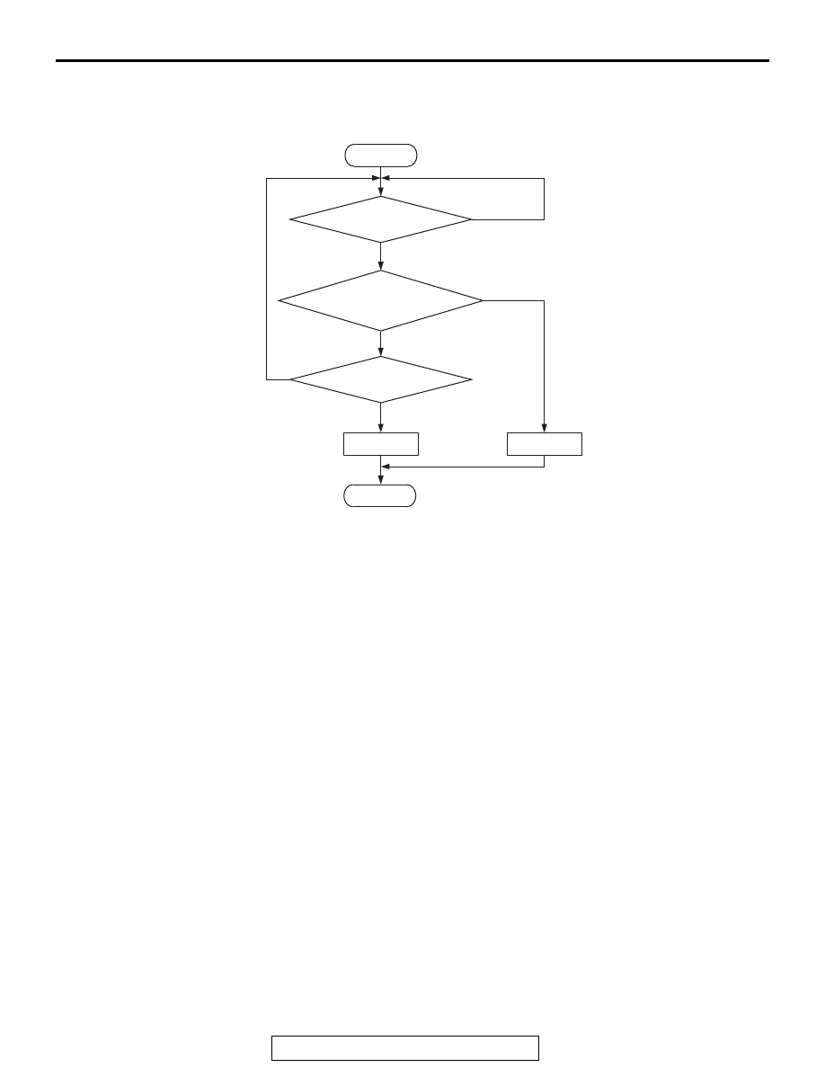
Logic Flow Chart
.
Check Conditions
• More than 350 seconds have passed since the
engine starting sequence was completed.
• Engine coolant temperature is higher than 7°C
(45
°F).
• Engine speed is higher than 1,200 r/min.
• Volumetric efficiency is higher than 30 percent.
• Throttle position sensor output voltage is lower
than 4 volts.
• Except while fuel is being shut off.
• Monitoring time: 30 seconds.
Judgement Criterion
• Right bank heated oxygen sensor (front) output
voltage does not get across lean/rich criteria
(about 0.5 volt) within about 30 seconds.
.
OBD-II DRIVE CYCLE PATTERN
Refer to Diagnostic Function
− OBD-II Drive Cycle −
Pattern 12
.
TROUBLESHOOTING HINTS (The most
likely causes for this code to be set are:)
• Right bank heated oxygen sensor (front) deterio-
rated.
• Harness damage
NOTE: When the right bank heated oxygen sensor
(front) begins to deteriorate, the heated oxygen sen-
sor output voltage will deviate from the voltage when
the sensor was new (normally 0.5 volt at stoichiomet-
ric ratio). This deviation will be corrected by the right
bank heated oxygen sensor (rear).
If the right bank heated oxygen sensor (rear)
responds poorly because it has deteriorated, it will
improperly correct the right bank heated oxygen sen-
sor (front). Thus, even when closed loop control is
being effected, the fluctuation of the right bank
heated oxygen sensor (front) output voltage
decreases, without intersecting with 0.5 volt. As a
result, there is a possibility of DTC P0134 becoming
registered.
.
• Open circuit in right bank injector.
• Connector damage.
• Exhaust leak.
• Air drawn in from gaps in gasket, seals, etc.
• Incorrect fuel pressure.
• ECM failed.
End
No
No
No
Malfunction
Good
30secs have passed?
AK704112
Start
Yes
Yes
Yes
Monitoring
conditions
Heated oxygen sensor
(front) output voltage
crosses lean/rich criteria?