Mitsubishi Outlander GS45X. Manual - part 778
MULTIPORT FUEL INJECTION (MFI) DIAGNOSIS
TSB Revision
MULTIPORT FUEL INJECTION (MFI) <3.0L ENGINE>
13B-45
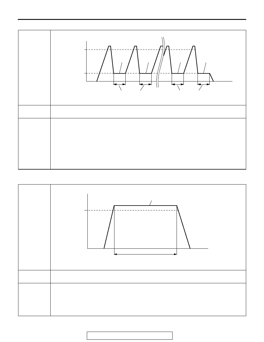
PATTERN 16
.
PATTERN 17
.
Drive cycle
pattern
Inspection
condition
Condition of A/T: Selector lever "D" range
Test
procedure
1. Start the engine with all the accessories switched OFF.
2. Accelerate until the vehicle speed is more than 50 km/h (31 mph).
3. Stop the vehicle in a safe place and let the engine idle for 20 seconds. (During the
monitor)
4. Repeat Steps 2 and 3 for 10 times.
5. Stop the vehicle in a safe place and turn the ignition switch to "LOCK" (OFF) position.
6. Start the engine and do Steps 1 to 5 again.
7. Confirm that the diagnostic trouble code (DTC) is not output.
AK402438
(3)
(2)
(1)
20 seconds
1st
mon-
itor
9th
mon-
itor
10th
mon-
itor
2nd
mon-
itor
Ignition
switch:
"LOCK" (OFF)
50 km/h
(31 mph)
Vehicle speed
AC
(3)
(2)
(2)
(3)
(3)
(2)
(5)
Idling
(2)
20 seconds
Time
Drive cycle
pattern
Inspection
conditions
• Engine coolant temperature: More than 20°C (68°F)
• Condition of A/T: Selector lever "D" range
Test
procedure
1. Start the engine with all the accessories switched OFF.
2. Drive the vehicle at more than 50 km/h (31 mph) for 30 seconds. (During the monitor)
3. Stop the vehicle in a safe place and turn the ignition switch to "LOCK" (OFF) position.
4. Start the engine and do Steps 1 to 3 again.
5. Confirm that the diagnostic trouble code (DTC) is not output.
AK402441
(2)
(1)
(3)
30 seconds
During the monitor
50 km/h
(31 mph)
Ignition
switch:
"LOCK" (OFF)
Vehicle speed
AP
Time