Mitsubishi Outlander GS45X. Manual - part 772
MULTIPORT FUEL INJECTION (MFI) DIAGNOSIS
TSB Revision
MULTIPORT FUEL INJECTION (MFI) <3.0L ENGINE>
13B-21
CONFIRMATION METHOD
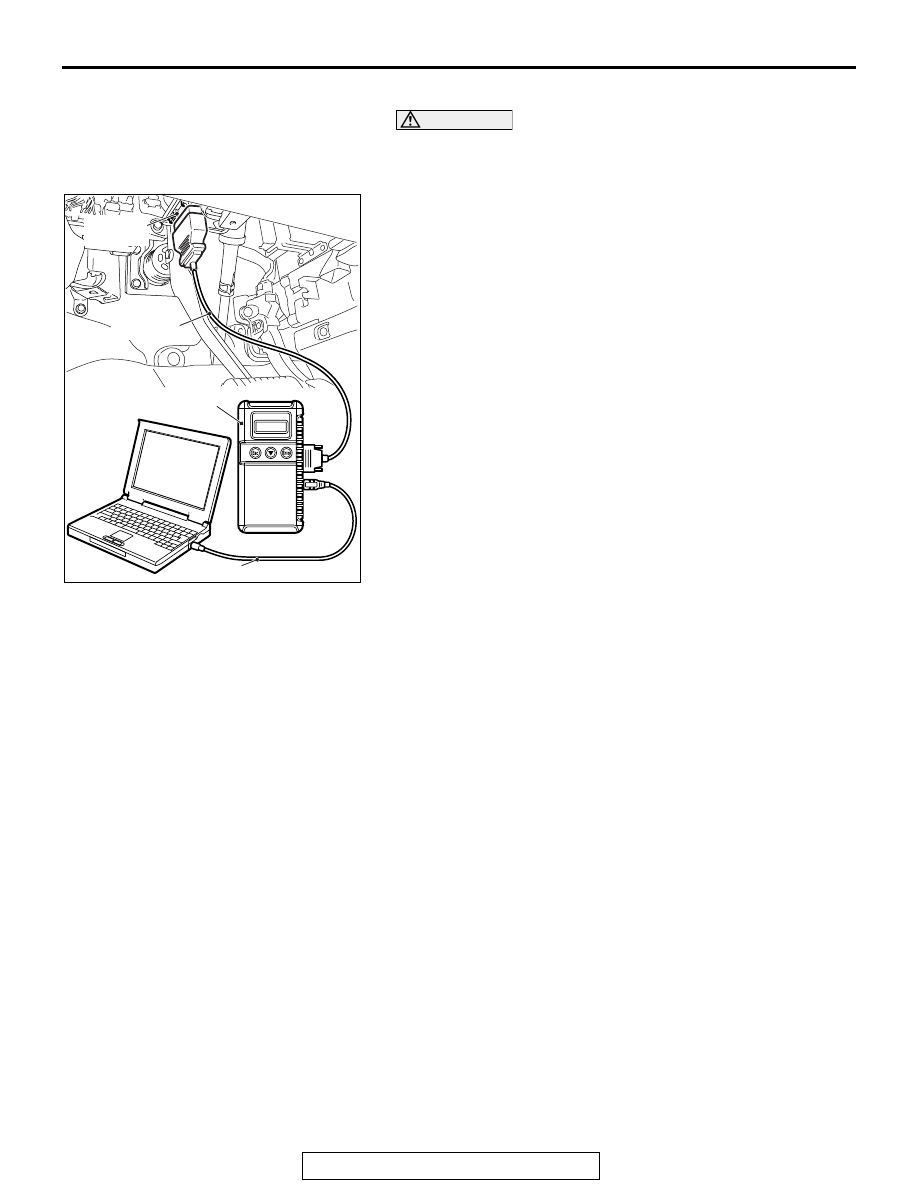
CAUTION
To prevent damage to scan tool MB991958, always turn the
ignition switch to the "LOCK" (OFF) position before con-
necting or disconnecting scan tool MB991958.
1. Connect scan tool MB991958 to the data link connector.
2. Turn the ignition switch to the "ON" position.
3. Select "System select."
4. Choose "from 2006 MY" under "MODEL YEAR".
5. Check that "Vehicle Information" contents are correct.
6. Choose "MFI".
7. Select "Special Function" from MFI Screen.
8. Select "Provisional DTCs" from Special Function Screen.
PERMANENT DTC
The permanent DTC(PDTC) is stored in the EEPROM of the
engine control module (ECM) as the permanent status, which
checks that the malfunction of the emission related compo-
nents/ the system has not been repaired yet. When detecting
the malfunction necessary to illuminate the malfunction indica-
tor lamp (SERVICE ENGINE SOON or Check Engine Lamp),
the ECM illuminates the MIL and stores the appropriate DTC as
the permanent DTC in the EEPROM concurrently. The usual
DTC is stored in the EEPROM aside from this. The ECM can
store up to 6 PDTCs. The ECM, therefore, cannot store the 7th
and subsequent PDTCs. If the temporary malfunction causes
the malfunction indicator lamp to be illuminated and then the
reinstatement during the subsequent driving causes it to be
extinguished, the PDTC is erased. Also if the ECM checks that
the DTC malfunction is fixed during the driving after the DTC
repair is completed, the PDTC is erased. The permanent DTC,
however, is not erased by disconnecting the battery terminal or
erasing with the scan tool (M.U.T-III). The permanent DTC can
be erased if all readiness statuses are erased or not completed
at the time of reprogramming the ECM. If must be erased while
the vehicle is repaired, the PDTC can be erased by the proce-
dures shown below. If must be erased because of the failure to
pass the Inspection and Maintenance (I/M) test, the permanent
DTC can also be erased by the following procedure:
.
AK700568AB
MB991824
MB991827
MB991910
Data link
connector