Mitsubishi Outlander GS45X. Manual - part 742


  Index      Mitsubishi     Mitsubishi Outlander GS45X - service repair manual


Search            


Content   ..  740  741  742  743   ..


Mitsubishi Outlander GS45X. Manual - part 742


MULTIPORT FUEL INJECTION (MFI) DIAGNOSIS

TSB Revision

MULTIPORT FUEL INJECTION (MFI) <2.4L ENGINE>

13A-791

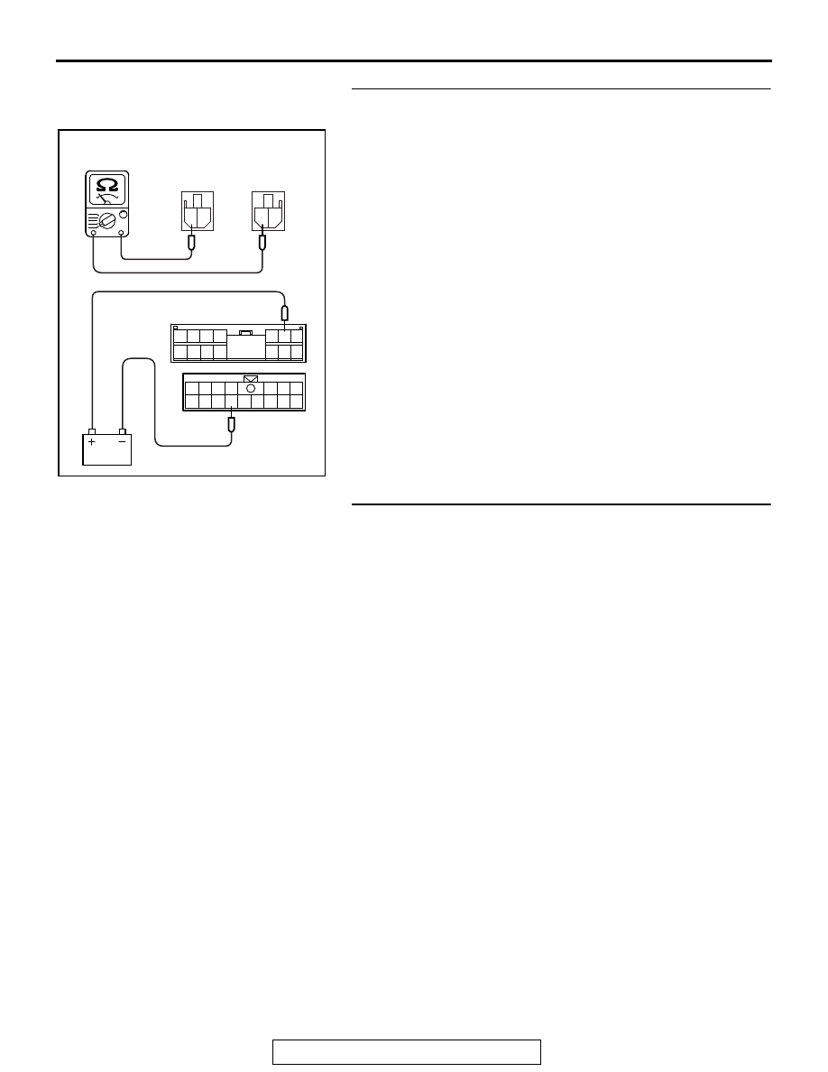
STEP 3. Check the fuel pump relay.
(1) Remove the ETACS-ECU.
(2) Use jumper wires to connect C-317 ETACS-ECU terminal 

No. 6 to the positive battery terminal and C-304 
ETACS-ECU terminal No. 11 to the negative battery 
terminal.

(3) Check for continuity between the C-307 ETACS-ECU 

terminal No. 1 and C-314 ETACS-ECU terminal No. 1 while 
connecting and disconnecting the jumper wire at the 
negative battery terminal.

• Continuity (2 Ω or less) <Negative battery terminal con-

nected>

• Should be open loop. <Negative battery terminal discon-

nected>

(4) Install the ETACS-ECU.
Q: Is the measured resistance normal?

YES : Go to Step 4.
NO :  Replace the ETACS-ECU. Then confirm that the 

malfunction symptom is eliminated.

STEP 4. Check harness connector B-11 at ECM connector 
for damage.
Q: Is the connector in good condition?

YES : Go to Step 5.
NO :  Repair or replace it. Refer to GROUP 00E, Harness 

Connector Inspection 

P.00E-2

. Then confirm that the 

malfunction symptom is eliminated.

1 2 3 4

5 6 7

8 9 10 11

131415

12

1 2

1 2

1

6

4

5

9

8

10 11

13

15

14

12

16

7

2 3

AK703917AC

C-314
ETACS-ECU
side connector

C-307
ETACS-ECU
side connector

C-304
ETACS-ECU
side connector

C-317 ETACS-ECU
side connector

MULTIPORT FUEL INJECTION (MFI) DIAGNOSIS

TSB Revision

MULTIPORT FUEL INJECTION (MFI) <2.4L ENGINE>

13A-792

STEP 5. Measure the power supply voltage at ECM 
connector B-11.
(1) Disconnect the connector B-11 and measure at the harness 

side.

(2) Turn the ignition switch to the "ON" position.
(3) Measure the voltage between terminal No. 96 and ground.

• Voltage should be battery positive voltage.

(4) Turn the ignition switch to the "LOCK" (OFF) position.
Q: Is battery positive voltage (approximately 12 volts) 

present?
YES : 
Go to Step 6.
NO :  Repair harness wire between ETACS-ECU connector 

C-304 (terminal No. 11) and ECM connector B-11 
(terminal No. 96) because of open circuit or short 
circuit to ground. Then confirm that the malfunction 
symptom is eliminated.

STEP 6. Measure the power supply voltage at ETACS-ECU 
connector C-307.
(1) Disconnect the connector C-307 and measure at the 

harness side.

(2) Turn the ignition switch to the "ON" position.
(3) Measure the voltage between terminal No. 1 and ground.

• Voltage should be battery positive voltage.

(4) Turn the ignition switch to the "LOCK" (OFF) position.
Q: Is battery positive voltage (approximately 12 volts) 

present?
YES : 
Go to Step 8.
NO :  Go to Step 7.

AK700221

71 72 73 74 75 76 77 78 79 80 81 82

83 84 85 86 87 88 89 90 91 92 93 94

95 96 97 98 99

100 101 102 103 104

112 113 114

109

108

107

110 111

115 116

106

105

118

117

82 81 80 79 78 77 76 75 74 73 72 71

94 93 92 91 90 89 88 87 86 85 84 83

99 98 97 96 95

100

101

102

103

104

105

106

112

113

114

109 108

107

110

111

115

116

117

118

AB

B-11 harness
connector:
component side 

1

2

AK604049 AB

C-307 harness
connector:
component side

MULTIPORT FUEL INJECTION (MFI) DIAGNOSIS

TSB Revision

MULTIPORT FUEL INJECTION (MFI) <2.4L ENGINE>

13A-793

STEP 7. Check harness connector A-33X at MFI relay 
connector for damage.
Q: Is the connector in good condition?

YES : Repair harness wire between MFI relay connector 

A-33X (terminal No. 2) and ETACS-ECU connector 
C-307 (terminal No. 1) because of open circuit or 
short circuit to ground. Then confirm that the 
malfunction symptom is eliminated.

NO :  Repair or replace it. Refer to GROUP 00E, Harness 

Connector Inspection 

P.00E-2

. Then confirm that the 

malfunction symptom is eliminated.

STEP 8. Check harness connector D-20 at fuel pump 
connector for damage.
Q: Is the connector in good condition?

YES : Go to Step 9.
NO :  Repair or replace it. Refer to GROUP 00E, Harness 

Connector Inspection 

P.00E-2

. Then confirm that the 

malfunction symptom is eliminated.

STEP 9. Check the fuel pump operation.
(1) Disconnect fuel pump connector D-20.
(2) Use jumper wires to connect fuel pump connector terminal 

No. 5 to the positive battery terminal and terminal No. 4 to 
the negative battery terminal.

• An operating sound of the fuel pump should be heard.

Q: Is the fuel pump operating properly?

YES : Go to Step 10.
NO :  Replace the fuel pump. Then confirm that the 

malfunction symptom is eliminated.

STEP 10. Check for continuity at fuel pump harness side 
connector D-20.
(1) Disconnect the connector D-20 and measure at the harness 

side.

(2) Check for the continuity between terminal No. 4 and 

ground.

• Should be less than 2 ohms.

Q: Does continuity exist?

YES : Go to Step 11.
NO :  Repair harness wire between fuel pump connector 

D-20 (terminal No. 4) and ground because of open 
circuit or harness damage. Then confirm that the 
malfunction symptom is eliminated.

AK604050

1 2 3

4 5

AB

Fuel pump side
connector

AK700218

1

2

3

4

5

AB

D-20 harness connector:
component side 

MULTIPORT FUEL INJECTION (MFI) DIAGNOSIS

TSB Revision

MULTIPORT FUEL INJECTION (MFI) <2.4L ENGINE>

13A-794

STEP 11. Measure the power supply voltage at fuel pump 
connector D-20.
(1) Disconnect the connector D-20 and measure at the harness 

side.

(2) Turn the ignition switch to the "ON" position.
(3) Measure the voltage between terminal No. 5 and ground.

• Voltage should be battery positive voltage.

(4) Turn the ignition switch to the "LOCK" (OFF) position.
Q: Is battery positive voltage (approximately 12 volts) 

present?
YES : 
Go to Step 13.
NO :  Go to Step 12.

STEP 12. Check for harness damage between ETACS-ECU 
connector C-304 (terminal No. 11) and ECM connector B-11 
(terminal No. 96)
Q: Is the harness wire in good condition?

YES : Replace the ECM. When the ECM is replaced, 

register the ID code. Refer to GROUP 42B, Diagnosis 
− ID Code Registration Judgment Table <Vehicles 

with KOS> 

P.42B-15

 or GROUP 42C, Diagnosis 

− ID 

Codes Registration Judgment Table <Vehicles with 
WCM> 

P.42C-10

. Then confirm that the malfunction 

symptom is eliminated.

NO :  Repair it. Then confirm that the malfunction symptom 

is eliminated.

STEP 13. Check harness connector A-33X at MFI relay 
connector for damage.
Q: Is the connector in good condition?

YES : Go to Step 14.
NO :  Repair or replace it. Refer to GROUP 00E, Harness 

Connector Inspection 

P.00E-2

. Then confirm that the 

malfunction symptom is eliminated.

STEP 14. Check for harness damage between MFI relay 
connector A-33X (terminal No. 2) and ETACS-ECU 
connector C-307 (terminal No. 1).
Q: Is the harness wire in good condition?

YES : Repair harness wire between ETACS-ECU connector 

C-314 (terminal No. 1) and fuel pump connector 
(terminal No. 5) because of harness damage. Then 
confirm that the malfunction symptom is eliminated.

NO :  Repair it. Then confirm that the malfunction symptom 

is eliminated.

AK704313

1

2

3

4

5

AB

D-20 harness connector:
component side 


Content   ..  740  741  742  743   ..