Mitsubishi Outlander GS45X. Manual - part 712


  Index      Mitsubishi     Mitsubishi Outlander GS45X - service repair manual


Search            


Content   ..  710  711  712  713   ..


Mitsubishi Outlander GS45X. Manual - part 712


MULTIPORT FUEL INJECTION (MFI) DIAGNOSIS

TSB Revision

MULTIPORT FUEL INJECTION (MFI) <2.4L ENGINE>

13A-671

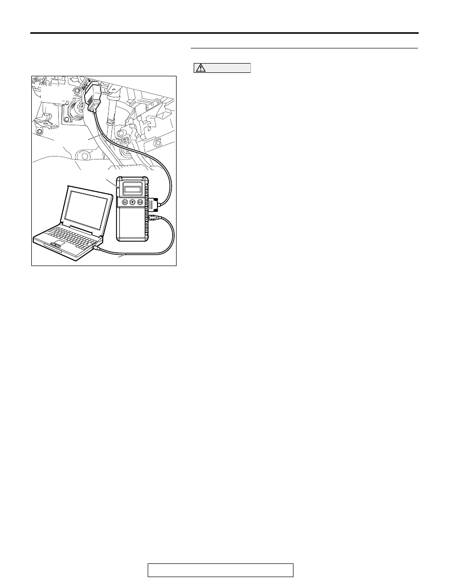
STEP 1. Test the OBD-II drive cycle.

CAUTION

To prevent damage to scan tool MB991958, always turn the 
ignition switch to the "LOCK" (OFF) position before con-
necting or disconnecting scan tool MB991958.
(1) Connect scan tool MB991958 to the data link connector.
(2) Turn the ignition switch to the "ON" position.
(3) Carry out the test drive with the drive cycle pattern. Refer to 

DIagnostic Function 

− OBD-II Drive Cycle − Pattern 23 

P.13A-11

.

(4) Check the diagnostic trouble code (DTC).
Q: Is DTC P2229 set?

YES : Replace the ECM. When the ECM is replaced, 

register the ID code. Refer to GROUP 42B, Diagnosis 
− ID Code Registration Judgment Table <Vehicles 

with KOS> 

P.42B-15

 or GROUP 42C, Diagnosis 

− ID 

Codes Registration Judgment Table <Vehicles with 
WCM> 

P.42C-10

NO :  It can be assumed that this malfunction is intermittent. 

Refer to GROUP 00, How to Use 
Troubleshooting/Inspection Service Points 

− How to 

Cope with Intermittent Malfunctions 

P.00-15

.

AK700568AB

MB991824

MB991827

MB991910

Data link
connector

MULTIPORT FUEL INJECTION (MFI) DIAGNOSIS

TSB Revision

MULTIPORT FUEL INJECTION (MFI) <2.4L ENGINE>

13A-672

DTC P2237: Linear Air-Fuel Ratio Sensor Positive Current Control Circuit/Open

1

2

3 4 5 6 7 8 9 10 11 12 13 14 15 16

17 18 19 20 21 22 23 24 25 26 27 28 29 30 31 32

33 34 35 36 37 38 39 40 41 42 43 44 45 46 47 48

49 50 51 52 53 54 55 56 57 58 59 60 61 62 63 64

P

3

2

1

6

5

4

AKA00449

1

12 13 14 15 16 1718 19 20 2122 2324

2 3 4 5

6 7 8 9 10 11

LINEAR AIR-FUEL RATIO SENSOR CIRCUIT

LINEAR 
AIR-FUEL 
RATIO 
SENSOR

FROM 
MFI RELAY

WHITE

BLA

CK

RED

WHITE

BLA

CK

RED

C-142

ENGINE
CONTROL
MODULE

38

39

56

4

5

1

14

20

21

2

6

3

B-10

A-12

AC

TO ECM TO ECM

AKA00842 AB

Connector: A-12

A-12

AK704090AB

Connector: B-10

B-10 (GR)

AK704089AD

Linear air-fuel
ratio sensor

SRS-ECU

Connector: C-142

C-142 (B)

MULTIPORT FUEL INJECTION (MFI) DIAGNOSIS

TSB Revision

MULTIPORT FUEL INJECTION (MFI) <2.4L ENGINE>

13A-673

.

CIRCUIT OPERATION

The linear air-fuel ratio sensor and the ECM are con-
nected by the following three lines to detect the 
air-fuel ratio.

• The line between the linear air-fuel ratio sensor 

(terminal No. 1) and the ECM (terminal No. 56) 
detects the air-fuel ratio. 

• The auxiliary line between the linear air-fuel ratio 

sensor (terminal No. 4) and the ECM (terminal 
No. 38) detects the air-fuel ratio.

• The line between the linear air-fuel ratio sensor 

(terminal No. 5) and the ECM (terminal No. 39) is 
connected to ground.

.

TECHNICAL DESCRIPTION

• The ECM effects air/fuel ratio feedback control in 

accordance with the signals from the linear 
air-fuel ratio sensor.

• If the linear air-fuel ratio sensor has deteriorated, 

corrections will be made by the heated oxygen 
sensor (rear).

.

DESCRIPTIONS OF MONITOR METHODS

• If the electrical currents of the ECM line are not 

detected although being supplied by the ECM, 
the DTC is stored as an open circuit.

.

MONITOR EXECUTION

Continuous

.

MONITOR EXECUTION CONDITIONS 
(Other monitor and Sensor)

Other Monitor (There is no temporary DTC stored 

in memory for the item monitored below)

• Linear air-fuel ratio sensor heater monitor

• Misfire monitor

• Fuel system monitor

Sensor (The sensor below is determined to be 

normal)

• Mass airflow sensor

• Engine coolant temperature sensor

• Intake air temperature sensor

• Barometric pressure sensor

• Throttle position sensor

• Accelerator pedal position sensor

.

MULTIPORT FUEL INJECTION (MFI) DIAGNOSIS

TSB Revision

MULTIPORT FUEL INJECTION (MFI) <2.4L ENGINE>

13A-674

DTC SET CONDITIONS
Logic Flow Chart

.

Check Conditions

• Battery positive voltage is between 10 and 16.5 

volts.

• More than 220 seconds have passed since the 

engine starting sequence was completed.

Judgement Criteria

• The negative circuit voltage subtracted from the 

pumping circuit voltage is be lower than 

−2.1 

volts or higher than 2.3 volts for 2 seconds.

• The pumping current is 0 milli ampere for 2 sec-

onds.

.

OBD-II DRIVE CYCLE PATTERN

Refer to Diagnosis Function 

− OBD-II Drive Cycle − 

Pattern 22 

P.13A-11

.

.

TROUBLESHOOTING HINTS (The most 
likely causes for this code to be set are:)

• Linear air-fuel ratio sensor failed.

• Open linear air-fuel ratio sensor circuit, or con-

nector damage.

• ECM failed.

End

No

No

No

Malfunction

(Positive circuit continuity)

Malfunction

(Circuit over voltage)

Good

Voltage diff*

> 2.3 V or < -2.1 V

*: Pumping circuit voltage 
   - Negative circuit voltage

AK900360

No

Start

Yes

Yes

Yes

Pumping current 

= 0 mA

No

Yes

Yes

Continuous failure 

for 2secs?

Continuous failure 

for 12secs?

Monitoring
conditions


Content   ..  710  711  712  713   ..