Mitsubishi Outlander GS45X. Manual - part 710


  Index      Mitsubishi     Mitsubishi Outlander GS45X - service repair manual


Search            


Content   ..  708  709  710  711   ..


Mitsubishi Outlander GS45X. Manual - part 710


MULTIPORT FUEL INJECTION (MFI) DIAGNOSIS

TSB Revision

MULTIPORT FUEL INJECTION (MFI) <2.4L ENGINE>

13A-663

DIAGNOSIS

Required Special Tools:

• MB991958: Scan tool (M.U.T.-III Sub Assembly)

• MB991824: V.C.I.

• MB991827: USB Cable

• MB991910: Main Harness A

STEP 1. Check harness connector C-123 at accelerator 
pedal position sensor for damage.
Q: Is the harness connector in good condition?

YES : Go to Step 2.
NO :  Repair or replace it. Refer to GROUP 00E, Harness 

Connector Inspection 

P.00E-2

. Then go to Step 16.

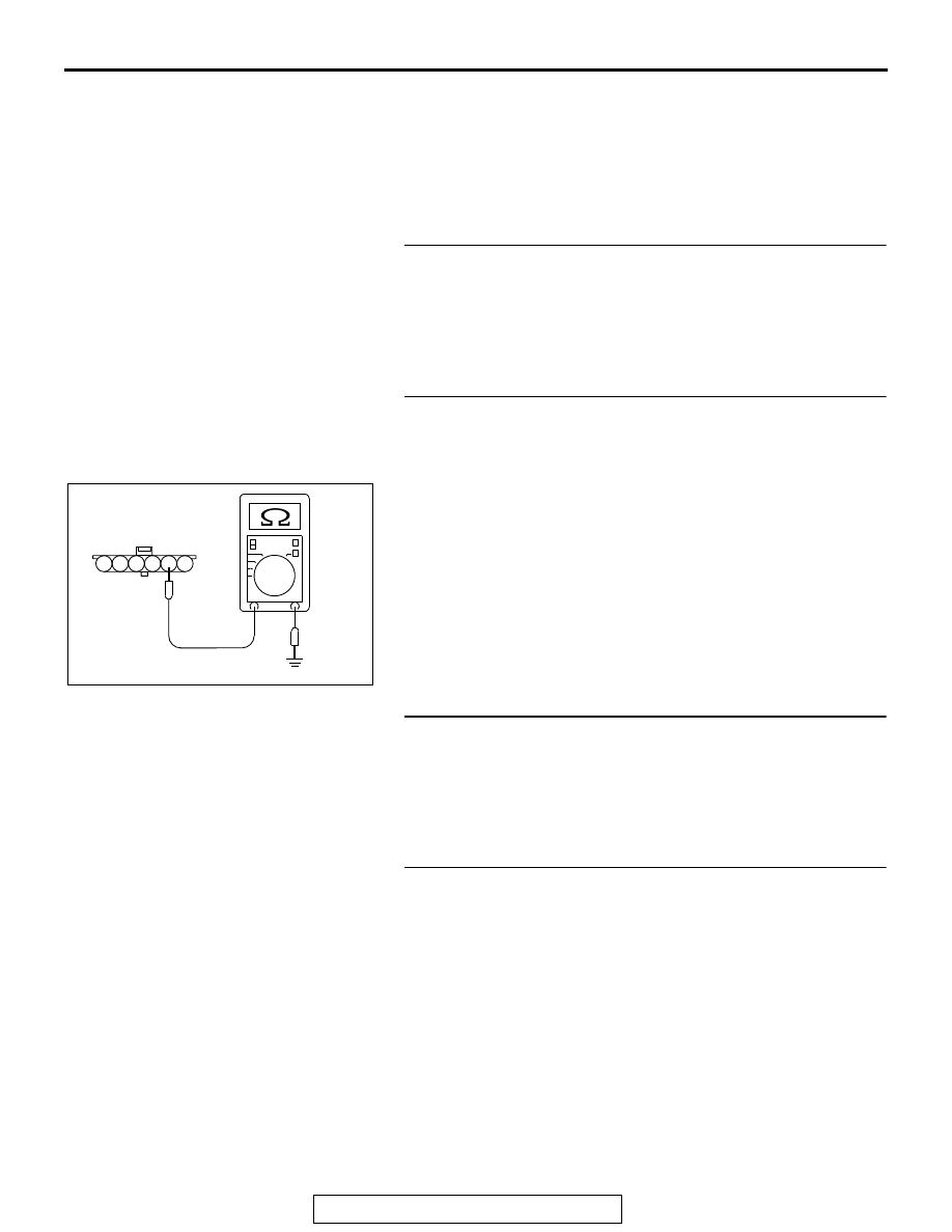
STEP 2. Check the continuity at accelerator pedal position 
sensor harness side connector C-123.
(1) Disconnect the connector C-123 and measure at the 

harness side.

(2) Measure the continuity between terminal No. 2 and ground.

• Continuity (2 ohms or less)

Q: Does continuity exist?

YES : Go to Step 6.
NO :  Go to Step 3.

STEP 3. Check harness connector B-11 at ECM for 
damage.
Q: Is the harness connector in good condition?

YES : Go to Step 4.
NO :  Repair or replace it. Refer to GROUP 00E, Harness 

Connector Inspection 

P.00E-2

. Then go to Step 16.

STEP 4. Check for harness damage between accelerator 
pedal position sensor connector C-123 (terminal No. 2) and 
ECM connector B-11 (terminal No. 76).
Q: Is the harness wire in good condition?

YES : Go to Step 5.
NO :  Repair it. Then go to Step 16.

AK604226

1

6 5 4 3 2

AB

C-123 harness
connector:
component side 

MULTIPORT FUEL INJECTION (MFI) DIAGNOSIS

TSB Revision

MULTIPORT FUEL INJECTION (MFI) <2.4L ENGINE>

13A-664

STEP 5. Using scan tool MB991958, read the diagnostic 
trouble code (DTC).

CAUTION

To prevent damage to scan tool MB991958, always turn the 
ignition switch to the "LOCK" (OFF) position before con-
necting or disconnecting scan tool MB991958.
(1) Connect scan tool MB991958 to the data link connector.
(2) Turn the ignition switch to the "ON" position.
(3) After the DTC has been deleted, read the DTC again.
(4) Turn the ignition switch to the "LOCK" (OFF) position.
Q: Is DTC P2138 set?

YES : Replace the ECM. When the ECM is replaced, 

register the ID code. Refer to GROUP 42B, Diagnosis 
− ID Code Registration Judgment Table <Vehicles 

with KOS> 

P.42B-15

 or GROUP 42C, Diagnosis 

− ID 

Codes Registration Judgment Table <Vehicles with 
WCM> 

P.42C-10

. Then go to Step 16.

NO :  It can be assumed that this malfunction is intermittent. 

Refer to GROUP 00, How to Use 
Troubleshooting/Inspection Service Points 

− How to 

Cope with Intermittent Malfunctions 

P.00-15

.

STEP 6. Check the continuity at accelerator pedal position 
sensor harness side connector C-123.
(1) Disconnect the connector C-123 and measure at the 

harness side.

(2) Measure the continuity between terminal No. 5 and ground.

• Continuity (2 ohms or less)

Q: Does continuity exist?

YES : Go to Step 10.
NO :  Go to Step 7.

STEP 7. Check harness connector B-11 at ECM for 
damage.
Q: Is the harness connector in good condition?

YES : Go to Step 8.
NO :  Repair or replace it. Refer to GROUP 00E, Harness 

Connector Inspection 

P.00E-2

. Then go to Step 16.

AK700568AB

MB991824

MB991827

MB991910

Data link
connector

AK604228

1

6 5 4 3 2

AB

C-123 harness
connector:
component side 

MULTIPORT FUEL INJECTION (MFI) DIAGNOSIS

TSB Revision

MULTIPORT FUEL INJECTION (MFI) <2.4L ENGINE>

13A-665

STEP 8. Check for harness damage between accelerator 
pedal position sensor connector C-123 (terminal No. 5) and 
ECM connector B-11 (terminal No. 79).
Q: Is the harness wire in good condition?

YES : Go to Step 9.
NO :  Repair it. Then go to Step 16.

STEP 9. Using scan tool MB991958, read the diagnostic 
trouble code (DTC).

CAUTION

To prevent damage to scan tool MB991958, always turn the 
ignition switch to the "LOCK" (OFF) position before con-
necting or disconnecting scan tool MB991958.
(1) Connect scan tool MB991958 to the data link connector.
(2) Turn the ignition switch to the "ON" position.
(3) After the DTC has been deleted, read the DTC again.
(4) Turn the ignition switch to the "LOCK" (OFF) position.
Q: Is DTC P2138 set?

YES : Replace the ECM. When the ECM is replaced, 

register the ID code. Refer to GROUP 42B, Diagnosis 
− ID Code Registration Judgment Table <Vehicles 

with KOS> 

P.42B-15

 or GROUP 42C, Diagnosis 

− ID 

Codes Registration Judgment Table <Vehicles with 
WCM> 

P.42C-10

. Then go to Step 16.

NO :  It can be assumed that this malfunction is intermittent. 

Refer to GROUP 00, How to Use 
Troubleshooting/Inspection Service Points 

− How to 

Cope with Intermittent Malfunctions 

P.00-15

.

STEP 10. Check harness connector B-11 at ECM for 
damage.
Q: Is the harness connector in good condition?

YES : Go to Step 11.
NO :  Repair or replace it. Refer to GROUP 00E, Harness 

Connector Inspection 

P.00E-2

. Then go to Step 16.

STEP 11. Check for harness damage between accelerator 
pedal position sensor connector C-123 (terminal No. 1) and 
ECM connector B-11 (terminal No. 75).
Q: Is the harness wire in good condition?

YES : Go to Step 12.
NO :  Repair it. Then go to Step 16.

AK700568AB

MB991824

MB991827

MB991910

Data link
connector

MULTIPORT FUEL INJECTION (MFI) DIAGNOSIS

TSB Revision

MULTIPORT FUEL INJECTION (MFI) <2.4L ENGINE>

13A-666

STEP 12. Check for harness damage between accelerator 
pedal position sensor connector C-123 (terminal No. 4) and 
ECM connector B-11 (terminal No. 78).
Q: Is the harness wire in good condition?

YES : Go to Step 13.
NO :  Repair it. Then go to Step 16.

STEP 13. Check for harness damage between accelerator 
pedal position sensor connector C-123 (terminal No. 3) and 
ECM connector B-11 (terminal No. 74).
Q: Is the harness wire in good condition?

YES : Go to Step 14.
NO :  Repair it. Then go to Step 16.

STEP 14. Check for harness damage between accelerator 
pedal position sensor connector C-123 (terminal No. 6) and 
ECM connector B-11 (terminal No. 77).
Q: Is the harness wire in good condition?

YES : Go to Step 15.
NO :  Repair it. Then go to Step 16.

STEP 15. Replace the accelerator pedal position sensor.
(1) Replace the accelerator pedal position sensor.
(2) Turn the ignition switch to the "ON" position.
(3) After the DTC has been deleted, read the DTC again.
(4) Turn the ignition switch to the "LOCK" (OFF) position.
Q: Is DTC P2138 set?

YES : Replace the ECM. When the ECM is replaced, 

register the ID code. Refer to GROUP 42B, Diagnosis 
− ID Code Registration Judgment Table <Vehicles 

with KOS> 

P.42B-15

 or GROUP 42C, Diagnosis 

− ID 

Codes Registration Judgment Table <Vehicles with 
WCM> 

P.42C-10

. Then go to Step 16.

NO :  The inspection is complete.


Content   ..  708  709  710  711   ..