Mitsubishi Outlander GS45X. Manual - part 707
MULTIPORT FUEL INJECTION (MFI) DIAGNOSIS
TSB Revision
MULTIPORT FUEL INJECTION (MFI) <2.4L ENGINE>
13A-651
TECHNICAL DESCRIPTION
• The accelerator pedal position sensor (sub) out-
puts voltage which corresponds to the accelera-
tor pedal depression.
• The ECM checks whether the voltage is within a
specified range.
.
DESCRIPTIONS OF MONITOR METHODS
Accelerator pedal position sensor (sub) output volt-
age is out of specified range.
.
MONITOR EXECUTION
Continuous
.
MONITOR EXECUTION CONDITIONS
(Other monitor and Sensor)
Other Monitor (There is no temporary DTC stored
in memory for the item monitored below)
• Not applicable
Sensor (The sensor below is determined to be
normal)
• Not applicable
.
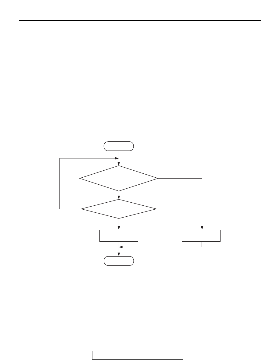
DTC SET CONDITIONS
Logic Flow Chart
.
Check Condition
• Ignition switch is "ON" position.
Judgement Criterion
• Accelerator pedal position sensor (sub) output
voltage is 2.5 volts or higher for 0.3 second.
.
OBD-II DRIVE CYCLE PATTERN
None.
.
TROUBLESHOOTING HINTS (The most
likely causes for this code to be set are:)
• Accelerator pedal position sensor failed.
• Open accelerator pedal position sensor (sub) cir-
cuit, harness damage, or connector damage.
• ECM failed.
AK604340
Good
Malfunction
End
No
No
Output voltage >= 2.5V
Start
Yes
Yes
Continuous
failure for 0.3sec