Mitsubishi Outlander GS45X. Manual - part 706


  Index      Mitsubishi     Mitsubishi Outlander GS45X - service repair manual


Search            


Content   ..  704  705  706  707   ..


Mitsubishi Outlander GS45X. Manual - part 706


MULTIPORT FUEL INJECTION (MFI) DIAGNOSIS

TSB Revision

MULTIPORT FUEL INJECTION (MFI) <2.4L ENGINE>

13A-647

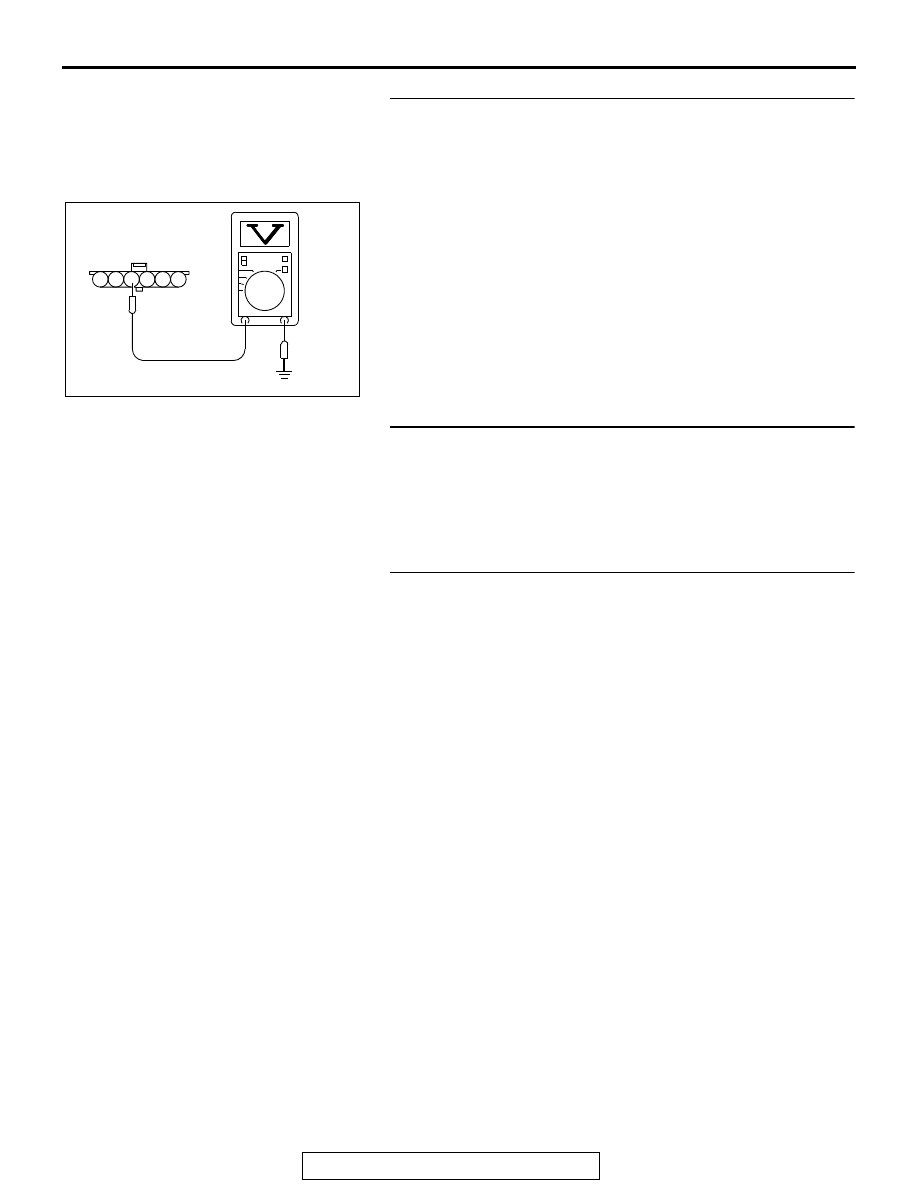
STEP 3. Measure the sensor supply voltage at accelerator 
pedal position sensor harness side connector C-123.
(1) Disconnect the connector C-123 and measure at the 

harness side.

(2) Turn the ignition switch to the "ON" position.
(3) Measure the voltage between terminal No. 4 and ground.

• Voltage should be between 4.9 and 5.1 volts.

(4) Turn the ignition switch to the "LOCK" (OFF) position.
Q: Is the measured voltage between 4.9 and 5.1 volts?

YES : Go to Step 7.
NO :   Go to Step 4.

STEP 4. Check harness connector B-11 at ECM for 
damage.
Q: Is the harness connector in good condition?

YES : Go to Step 5.
NO :  Repair or replace it. Refer to GROUP 00E, Harness 

Connector Inspection 

P.00E-2

. Then go to Step 11.

STEP 5. Check for open circuit and short circuit to ground 
between accelerator pedal position sensor connector 
C-123 (terminal No. 4) and ECM connector B-11 (terminal 
No. 78).
Q: Is the harness wire in good condition?

YES : Go to Step 6.
NO :  Repair it. Then go to Step 11.

AK604227

1

6 5 4 3 2

AB

C-123 harness
connector:
component side 

MULTIPORT FUEL INJECTION (MFI) DIAGNOSIS

TSB Revision

MULTIPORT FUEL INJECTION (MFI) <2.4L ENGINE>

13A-648

STEP 6. Using scan tool MB991958, check data list item 12: 
Accelerator Pedal Position Sensor (sub).
(1) Turn the ignition switch to the "ON" position.
(2) Set scan tool MB991958 to the data reading mode for item 

12, Accelerator Pedal Position Sensor (sub).

• Output voltage is between 0.4 and 0.6 volt when foot is 

released from accelerator pedal.

• Output voltage is 2.0 volts or higher when accelerator 

pedal is fully depressed.

(3) Turn the ignition switch to the "LOCK" (OFF) position.
Q: Is the sensor operating properly?

YES : It can be assumed that this malfunction is intermittent. 

Refer to GROUP 00, How to Use 
Troubleshooting/Inspection Service Points 

− How to 

Cope with Intermittent Malfunctions 

P.00-15

.

NO :  Replace the ECM. When the ECM is replaced, 

register the ID code. Refer to GROUP 42B, Diagnosis 
− ID Code Registration Judgment Table <Vehicles 

with KOS> 

P.42B-15

 or GROUP 42C, Diagnosis 

− ID 

Codes Registration Judgment Table <Vehicles with 
WCM> 

P.42C-10

. Then go to Step 11.

STEP 7. Check harness connector B-11 at ECM for 
damage.
Q: Is the harness connector in good condition?

YES : Go to Step 8.
NO :  Repair or replace it. Refer to GROUP 00E, Harness 

Connector Inspection 

P.00E-2

. Then go to Step 11.

STEP 8. Check for harness damage between accelerator 
pedal position sensor connector C-123 (terminal No. 4) and 
ECM connector B-11 (terminal No. 78).
Q: Is the harness wire in good condition?

YES : Go to Step 9.
NO :  Repair it. Then go to Step 11.

STEP 9. Check for open circuit, short circuit to ground and 
harness damage between accelerator pedal position 
sensor connector C-123 (terminal No. 6) and ECM 
connector B-11 (terminal No. 77)
Q: Is the harness wire in good condition?

YES : Go to Step 10.
NO :  Repair it. Then go to Step 11.

MULTIPORT FUEL INJECTION (MFI) DIAGNOSIS

TSB Revision

MULTIPORT FUEL INJECTION (MFI) <2.4L ENGINE>

13A-649

STEP 10. Replace the accelerator pedal position sensor.
(1) Replace the accelerator pedal position sensor.
(2) Turn the ignition switch to the "ON" position.
(3) After the DTC has been deleted, read the DTC again.
(4) Turn the ignition switch to the "LOCK" (OFF) position.
Q: Is DTC P2127 set?

YES : Replace the ECM. When the ECM is replaced, 

register the ID code. Refer to GROUP 42B, Diagnosis 
− ID Code Registration Judgment Table <Vehicles 

with KOS> 

P.42B-15

 or GROUP 42C, Diagnosis 

− ID 

Codes Registration Judgment Table <Vehicles with 
WCM> 

P.42C-10

. Then go to Step 11.

NO :  The inspection is complete.

STEP 11. Using scan tool MB991958, read the diagnostic 
trouble code (DTC).
(1) Turn the ignition switch to the "ON" position.
(2) After the DTC has been deleted, read the DTC again.
(3) Turn the ignition switch to the "LOCK" (OFF) position.
Q: Is DTC P2127 set?

YES : Retry the troubleshooting.
NO :  The inspection is complete.

MULTIPORT FUEL INJECTION (MFI) DIAGNOSIS

TSB Revision

MULTIPORT FUEL INJECTION (MFI) <2.4L ENGINE>

13A-650

DTC P2128: Accelerator Pedal Position Sensor (sub) Circuit High Input

.

CIRCUIT OPERATION

• A 5-volt power supply is applied on the accelera-

tor pedal position sensor (sub) power terminal 
(terminal No. 4) from the ECM (terminal No. 78).

• A voltage that is according to the accelerator 

opening angle is sent to the ECM (terminal No. 
77) from the accelerator pedal position sensor 
(sub) output terminal (terminal No. 6).

• The ground terminal (terminal No. 5) is grounded 

with ECM (terminal No. 79).

.

AK604257

71 72 73 74 75 76 77 78 79 80 81 82

83 84 85 86 87 88 89 90 91 92 93 94

95 96 97 98 99

100 101 102 103 104

112 113 114

109

108

107

110 111

115 116

106

105

118

117

6

1 2 3 4 5

AF

5 V

78

4

YELLO

W

-RED

YELLOE-BLUE

77

79

6

5

B-11

C-123

HALL IC

ENGINE
CONTROL
MODULE

ACCELERATOR PEDAL POSITION SENSOR (SUB) CIRCUIT

ACCELERATOR PEDAL
POSITION SENSOR (SUB)

BLA

CK-WHITE

AK704097AB

Connector: B-11

B-11 (GR)

AK704152

AB

Accelerator pedal
position sensor  

Connector: C-123

C-123 (B)


Content   ..  704  705  706  707   ..